Evaporative refrigerant condenser heat exchanger

a heat exchanger and refrigerant technology, applied in refrigeration and liquidation, refrigeration machines, lighting and heating apparatus, etc., can solve the problems of significantly reducing the thermal performance and efficiency return of conventional serpentine coil evaporative condensers, material cost and weight, etc., to reduce the potential travel distance, reduce the length of the circuit, and increase the number of circuits

Inactive Publication Date: 2019-02-14
EVAPCO
View PDF5 Cites 1 Cited by
  • Summary
  • Abstract
  • Description
  • Claims
  • Application Information

AI Technical Summary

Benefits of technology

[0008]Increasing the number of circuits and reducing the circuit length has several benefits. First, it reduces the potential travel distance required for condensate to exit the coil. For example, refrigerant that condensed at the mid-point of the first pass must travel through the remaining passes in order to exit the coil, potentially occupying internal tube wall area that could otherwise be used for further condensing.
[0009]Second, the presence of additional circuits at the inlet of the heat exchanger will improve the distribution of vapor throughout the coil. This is clearly evident when comparing a conventional four-pass serpentine coil circuit to the equivalent coil with the proposed improvements in FIG. 5. For example, condensate that forms at the mid-point of the bottom pass of a convention serpentine coil will be replaced with vapor that mus

Problems solved by technology

Manufacturers of conventional evaporative refrigerant condensers have largely applied the aforementioned methods up to the practical physical limitations concerning power consumption, fan blade speed, and material

Method used


Image

  • Evaporative refrigerant condenser heat exchanger
  • Evaporative refrigerant condenser heat exchanger
  • Evaporative refrigerant condenser heat exchanger

Examples


Embodiment Construction

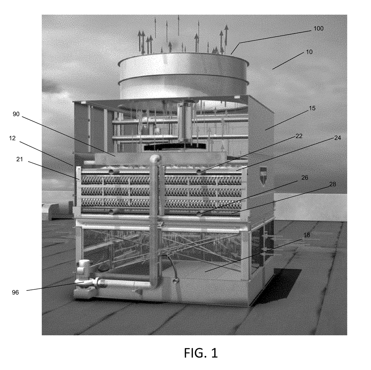
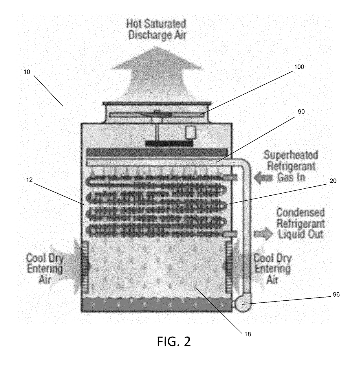
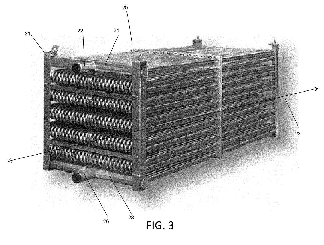
[0017]This inventions relates particularly to condenser coil bundles used in evaporative refrigerant condensers 10 of the type shown in FIGS. 1 and 2 configured to indirectly transfer heat between a superheated refrigerant and ambient air, operative in a wet mode or a dry mode as described below depending on ambient atmospheric conditions, such as temperature, humidity and pressure.

[0018]The apparatus 10 includes a fan 100 for causing air to flow through the apparatus, and as shown schematically in FIG. 1, sitting atop housing 15. At normal ambient atmospheric conditions where freezing of the cooling liquid, typically water, is not of concern, air is drawn into the plenum 18 of the apparatus via air passages at the bottom of the unit through the open air intake dampers, and enters the evaporative heat transfer section 12 where heat transfer takes place involving the distribution of water from a water distribution assembly 90 driven by a pump 96. When the ambient temperature and the ...


PUM


Abstract

A coil assembly for an evaporative refrigerant condenser having a plurality of nested pairs of serpentine heat exchange tubes tightly packed adjacent to one-another; each nested pair of serpentine heat exchange tubes having an outer serpentine tube and an inner serpentine tube having an identical number of straight lengths and having parallel vertical and horizontal axes.

Description

BACKGROUND OF THE INVENTIONField of the Invention[0001]The present invention relates to evaporative refrigerant condenser coils.Description of the Background[0002]A conventional evaporative refrigerant condenser is comprised of a fan system, water distribution system and heat exchanger. The heat exchanger is generally comprised of multiple circuits of tube. Individual circuits are formed into serpentines with a specified number of passes, typically by bending a continuous length of tube. Individual circuits are joined in parallel by common inlet and outlet manifolds.[0003]The predominant methods of increasing heat rejection capacity for a given plan area are to increase the airflow rate over the heat exchanger by increasing the fan speed and power, and to increase the heat exchanger surface area by creating serpentines with more passes from longer lengths of tube.SUMMARY OF THE INVENTION[0004]Manufacturers of conventional evaporative refrigerant condensers have largely applied the a...

Claims


Application Information

Patent Timeline
IPC IPC(8): F25B39/04
CPCF25B39/04F25B2339/041F25B2339/047F25B39/00F25B39/02
Inventor HESSER, NICHOLAS
Owner EVAPCO
Why Eureka
Try Eureka