Spiral computed tomography device

a computed tomography and spiral technology, applied in the direction of measurement devices, material analysis by transmitting radiation, instruments, etc., can solve the problems of x-ray tube and mounting substrate interference, difficult to photograph plate-shaped work such as mounting substrate in a magnified view, and achieve high precision and efficient performance

Active Publication Date: 2019-02-14
SHIMADZU CORP
View PDF4 Cites 27 Cited by
  • Summary
  • Abstract
  • Description
  • Claims
  • Application Information

AI Technical Summary

Benefits of technology

[0017]With the oblique CT apparatus of the present invention, images can be assessed from a group of cross-sectional images (resulting from provisional CT imaging), so even an unskilled person can determine a specific cross-sectional image (for example, a cross-sectional image at the focus point height) with high precision and can further determine the CT imaging conditions (so that the cross-sectional image is positioned in the cent

Problems solved by technology

In comparison to an oblique CT apparatus, an orthogonal type apparatus can achieve a clear image with little distortion, but there is a drawback in that it is difficult to photograph a plate-shaped work such as a mounting substrate in a magnified view.
However, since the mounting substrate has a wide shape in the planar direction, there is a risk

Method used


Image

  • Spiral computed tomography device
  • Spiral computed tomography device
  • Spiral computed tomography device

Examples


embodiments

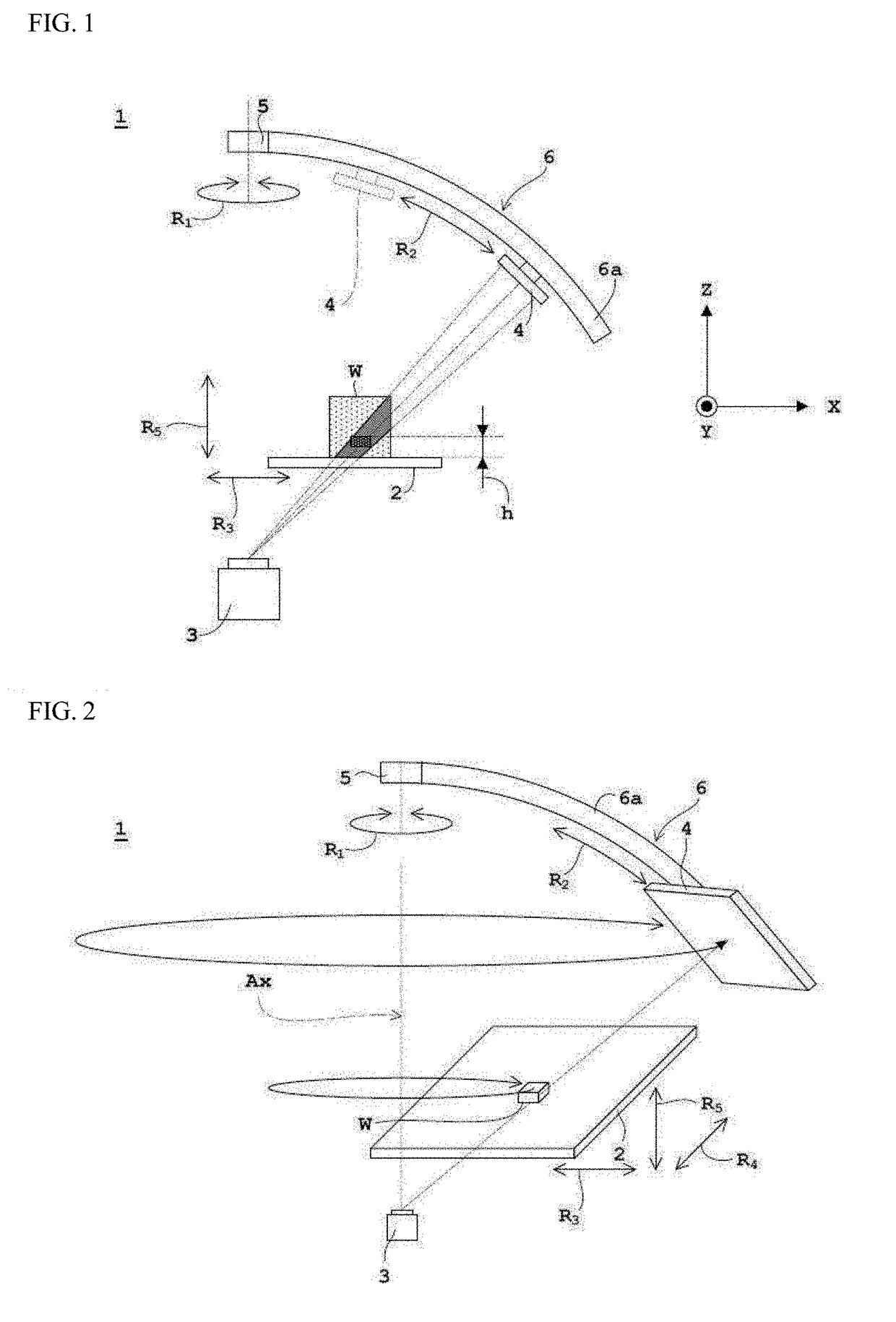
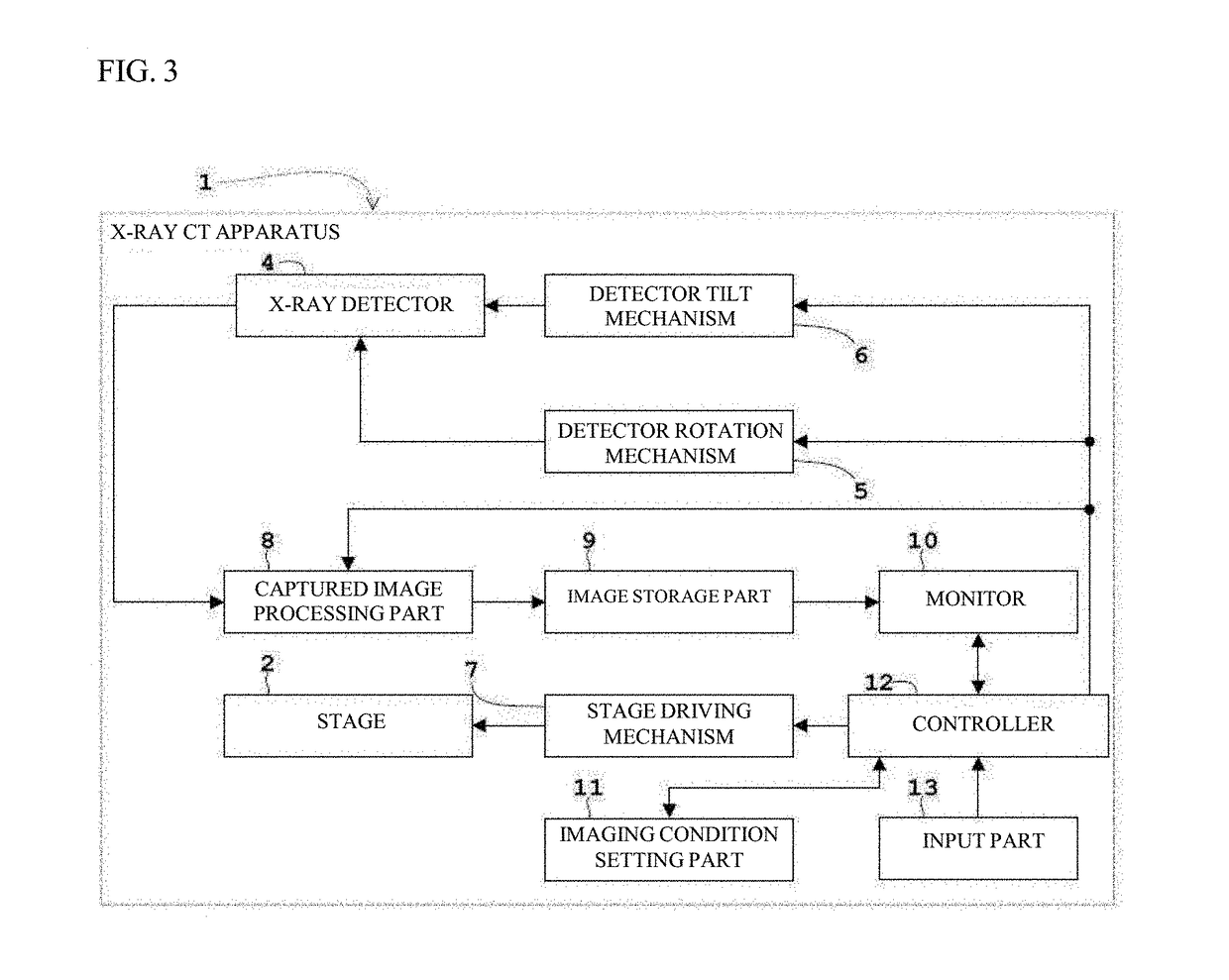
[0033]Embodiments of the present invention will be described hereinafter with reference to the drawings. FIG. 1 is a schematic block diagram of an X-ray CT apparatus according to an embodiment. FIG. 2 is a schematic perspective view of an X-ray CT apparatus according to an embodiment. FIG. 3 is a block diagram of an X-ray CT apparatus according to an embodiment. In this embodiment, an X-ray CT apparatus will be described as an example of an X-ray CT apparatus, and a micro-focus X-ray CT apparatus capable of observing the three-dimensional structure inside an object (work) at high magnification will be described as an example of an X-ray CT apparatus.

[0034]As illustrated in FIG. 18, an X-ray CT apparatus 1 includes a stage 2 on which a work W is mounted, and an X-ray tube 3 and an X-ray detector 4 disposed facing one another so as to sandwich the stage 2 there between. The X-ray detector 4 is not particularly limited and may be, for example, an image intensifier (I. I.), a flat panel...


PUM


Abstract

When performing CT imaging while maintaining a state in which a rotational axis Ax and an irradiation axis (optical axis) intersect obliquely, the X-ray CT apparatus 1 of the present invention can make assessments from a group of cross-sectional images resulting from provisional CT imaging, so even an unskilled person can determine a specific cross-sectional image with high precision, and can further determine the CT imaging conditions so that the cross-sectional image is positioned in the center. In addition, by performing main imaging by narrowing the target field from provisional CT imaging, CT imaging can be performed without the portion to be viewed deviating from the field of view. As a result, the operator can perform CT imaging without repeating a process of trial and error involving performing CT imaging while changing the CT imaging conditions, and CT imaging can be performed efficiently without requiring skill.

Description

TECHNICAL FIELD[0001]The present invention relates to an oblique CT apparatus for performing CT (Computed Tomography) imaging.BACKGROUND ART[0002]CT apparatuses can be broadly divided into a type known as orthogonal CT and type known as oblique CT or planar CT (PCT: Planar Computed Tomography). An X-ray CT apparatus may be give as an example of a CT apparatus, and in an orthogonal type of apparatus, a rotational axis around which an object (work) is driven to rotate and a irradiation axis connecting the centers of an X-ray source (for example, an X-ray tube) and an X-ray detector are orthogonal. In contrast, in an apparatus called an oblique CT, the rotational axis and the irradiation axis (optical axis) are not orthogonal, but rather intersect obliquely (for example, see Patent Document 1).[0003]In comparison to an oblique CT apparatus, an orthogonal type apparatus can achieve a clear image with little distortion, but there is a drawback in that it is difficult to photograph a plat...

Claims


Application Information

Patent Timeline
IPC IPC(8): G01N23/046
CPCG01N23/046G06F3/0482G06F3/04847G06F3/04845G01N2223/33G01N23/04
Inventor IWAO, YOSHIHIKO
Owner SHIMADZU CORP
Why Eureka
Try Eureka