
Active surge chamber

a technology of active surge and chamber, which is applied in the direction of positive displacement liquid engine, fluid pressure control, instruments, etc., can solve the problems of system prone to unwanted oscillation and pumps that do not maintain such a stable pressure output, and achieve the effect of relieving fluid pressur

Active Publication Date: 2019-02-14
CARLISLE FLUID TECH INC
View PDF12 Cites 3 Cited by
  • Summary
  • Abstract
  • Description
  • Claims
  • Application Information

AI Technical Summary

Benefits of technology

The present invention relates to a piston for a pneumatic valve control system. The piston has a specific spring rate that reduces the likelihood of hunting, which is unwanted oscillation. The goal is to keep the diaphragm positioned near a neutral position during operation. The piston increases the surface area on which the fluid pressure acts, which allows higher pressure ratios and higher paint flow pressures without changing the fluid pressure. This means that the system can handle higher flow rates of paint.

Problems solved by technology

However other pumps exist that do not maintain such a stable pressure output over a single stroke, such as diaphragm pumps.
When current active surge chambers are used in combination with these types of pumps the system is prone to unwanted oscillation, so called ‘hunting’.

Method used


Image

  • Active surge chamber
  • Active surge chamber
  • Active surge chamber

Examples


Embodiment Construction

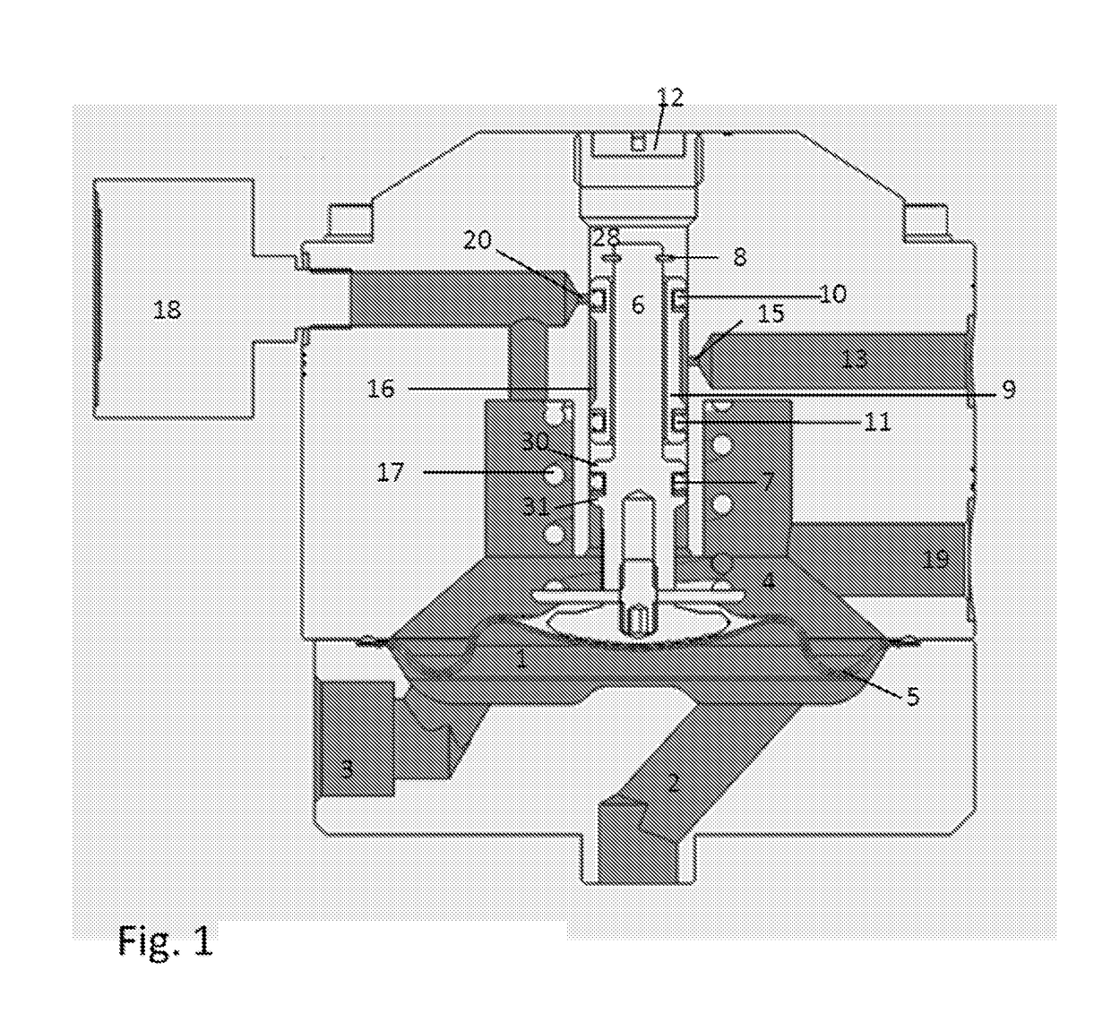
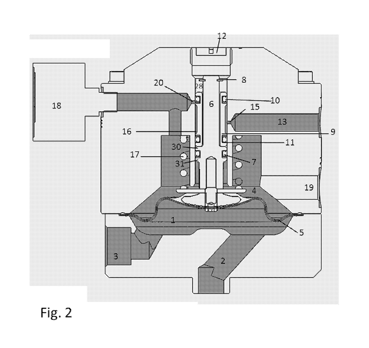
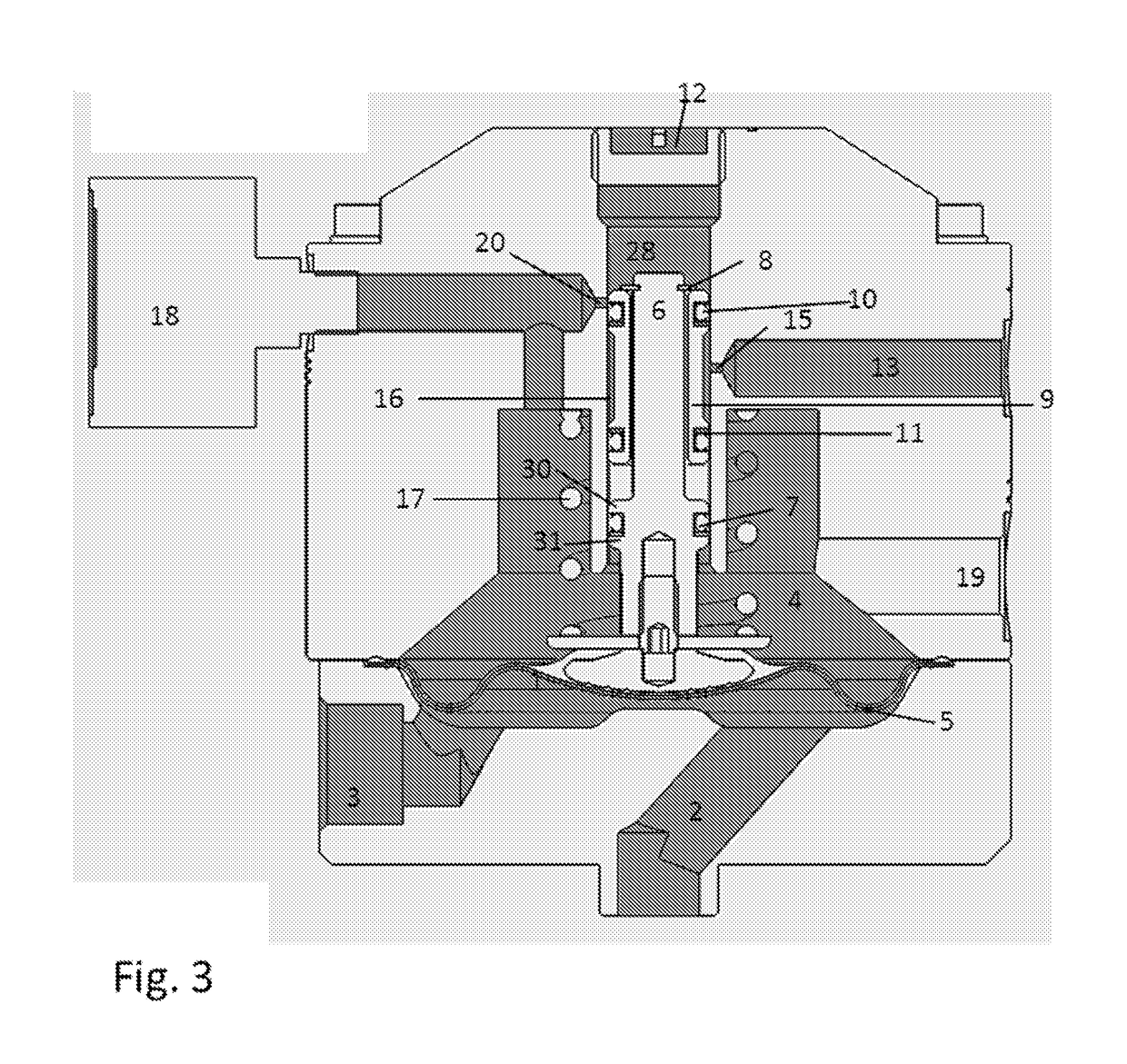
[0039]With reference to FIGS. 1-3, there is illustrated an active surge chamber for use with a diaphragm pump.

[0040]There is a paint channel 1 which may be fed by a diaphragm pump (not shown). In the embodiment shown the paint may flow into the paint channel 1 via a conduit 2, and flow out via a conduit 3. In other embodiments there may only one conduit that is connected to the paint supply system in a “tee” arrangement where paint flows in and out through the same conduit. The paint channel 1 is separated from 4 by a flexible diaphragm 5 that is secured and sealed such that the chamber fluid and paint in paint channel 1 are never in contact. The chamber fluid is typically compressed air, and will be referred to as air in the following description. However other fluids could be used, such as another gas or a hydraulic fluid.

[0041]A shaft 6 is attached to the diaphragm 5 and contained in a bore 28. A shaft seal 7, end flange 8, and pair of seal flanges 30, 31 are situated on the shaf...


PUM


Abstract

An active surge chamber for use in a paint supply system comprising a paint channel, a fluid chamber connected to a pressurised fluid supply, a diaphragm, a spring, and means responsive to movement of the diaphragm for effecting connection and disconnection of the pressurised fluid supply to the fluid chamber and for relieving pressure of fluid in the chamber. The paint channel is sealingly separated from the fluid chamber by the diaphragm. The spring has a spring rate such that the force exerted on the diaphragm by the spring restricts movement of the diaphragm over a selected range of pump outlet pressures in order to attenuate the movement of the diaphragm and reduce the susceptibility of the system to unwanted oscillation. Pressure fluctuations in a paint flow induced by usage of a reciprocating pump upstream of the active surge chamber are minimised.

Description

FIELD OF THE INVENTION[0001]The present invention relates to an active surge chamber suitable for use with reciprocating pumps in paint supply systems.BACKGROUND TO THE INVENTION[0002]In paint supply systems it is common to use a reciprocating pump to move paint throughout the system. A reciprocating pump typically consists of a piston that is positioned inside a cylinder. The piston is driven in a reciprocating motion inside the cylinder. A pumping action is provided to pump paint, or any other fluid, with the aid of an inlet and outlet valve. When the piston is driven in one direction during ‘the upstroke,’ paint is pulled into the cylinder via the inlet valve while the outlet valve is closed. When the cylinder is driven in the opposite direction during ‘the downstroke,’ paint is pushed out of the cylinder via the outlet valve while the inlet valve is closed. Therefore as paint passes through the reciprocating pump kinetic energy is transferred from the piston to the paint in orde...

Claims


Application Information

Patent Timeline
IPC IPC(8): G05D16/06F04B11/00
CPCG05D16/0688F04B11/0033F04B43/067B05B7/1459F04B11/0008F04B11/0016F04B43/02
Inventor ROGERS, JOHN ANTHONY
Owner CARLISLE FLUID TECH INC
Learn More