Varying exposure time of pixels in photo sensor using motion prediction

a technology of motion prediction and exposure time, applied in the field of photo sensors, can solve the problems of reducing the signal that is available to be captured, over-exposure of some photo sensors, and under-exposure of other photos

Active Publication Date: 2019-02-14
META PLATFORMS TECH LLC
View PDF4 Cites 28 Cited by
  • Summary
  • Abstract
  • Description
  • Claims
  • Application Information

AI Technical Summary

Problems solved by technology

The matrix and its wiring, however, reflect some of the light, reducing the signal that is available to be captured.
The same exposure time for different photo sensors may result in over-exposure for some of the photo sensors and under-exposure for other photo sensors

Method used


Image

  • Varying exposure time of pixels in photo sensor using motion prediction
  • Varying exposure time of pixels in photo sensor using motion prediction
  • Varying exposure time of pixels in photo sensor using motion prediction

Examples


example method

of Varying Exposure Times for Pixel Blocks Using Prediction

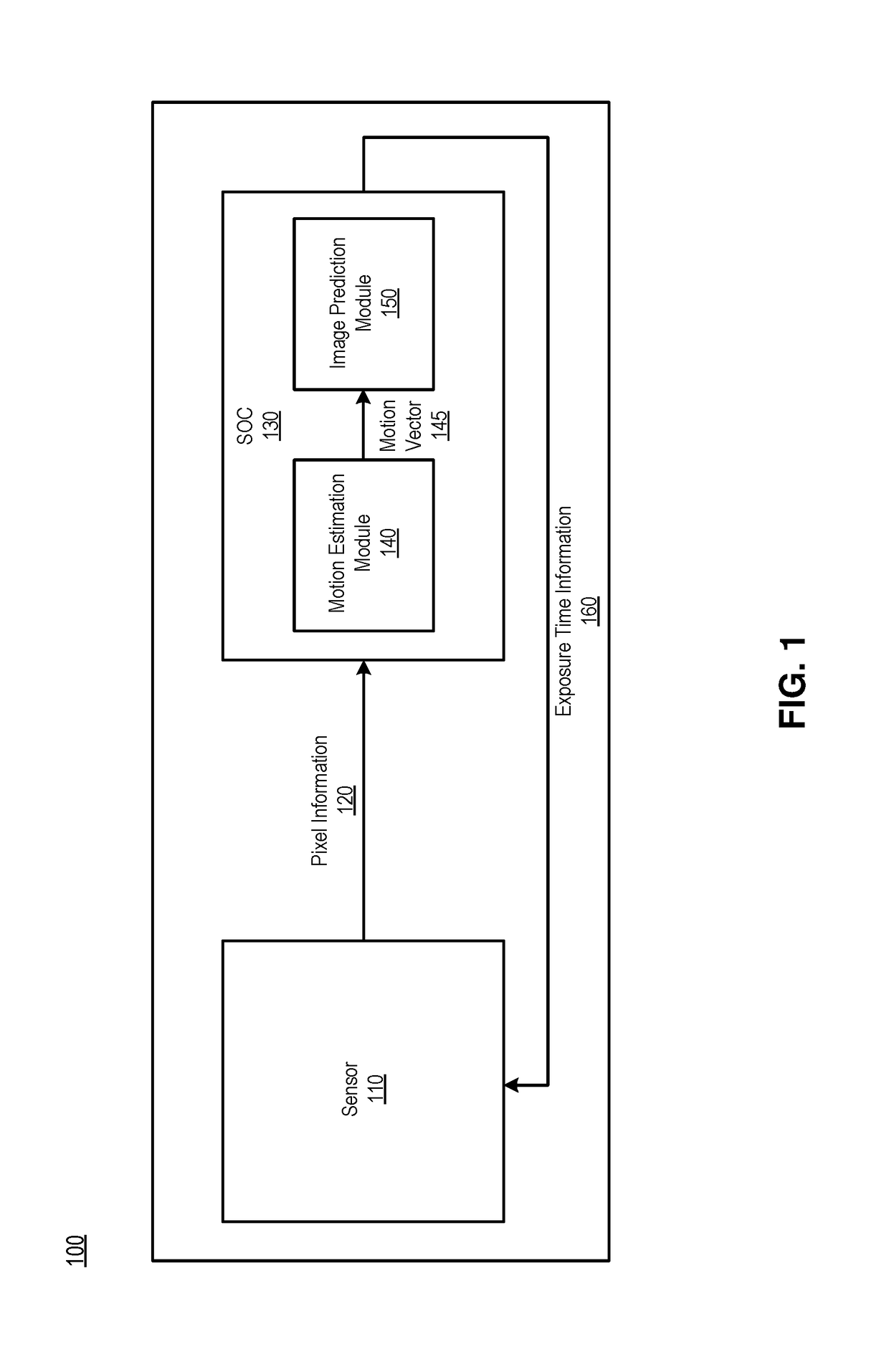
[0055]FIG. 7 is a flowchart illustrating a method of exposure time variation using prediction, according to one embodiment. A system on chip (SOC) including a motion estimation module and an image prediction module generates 700 exposure time information by performing motion prediction on prior frames captured by pixels before capturing a current frame.

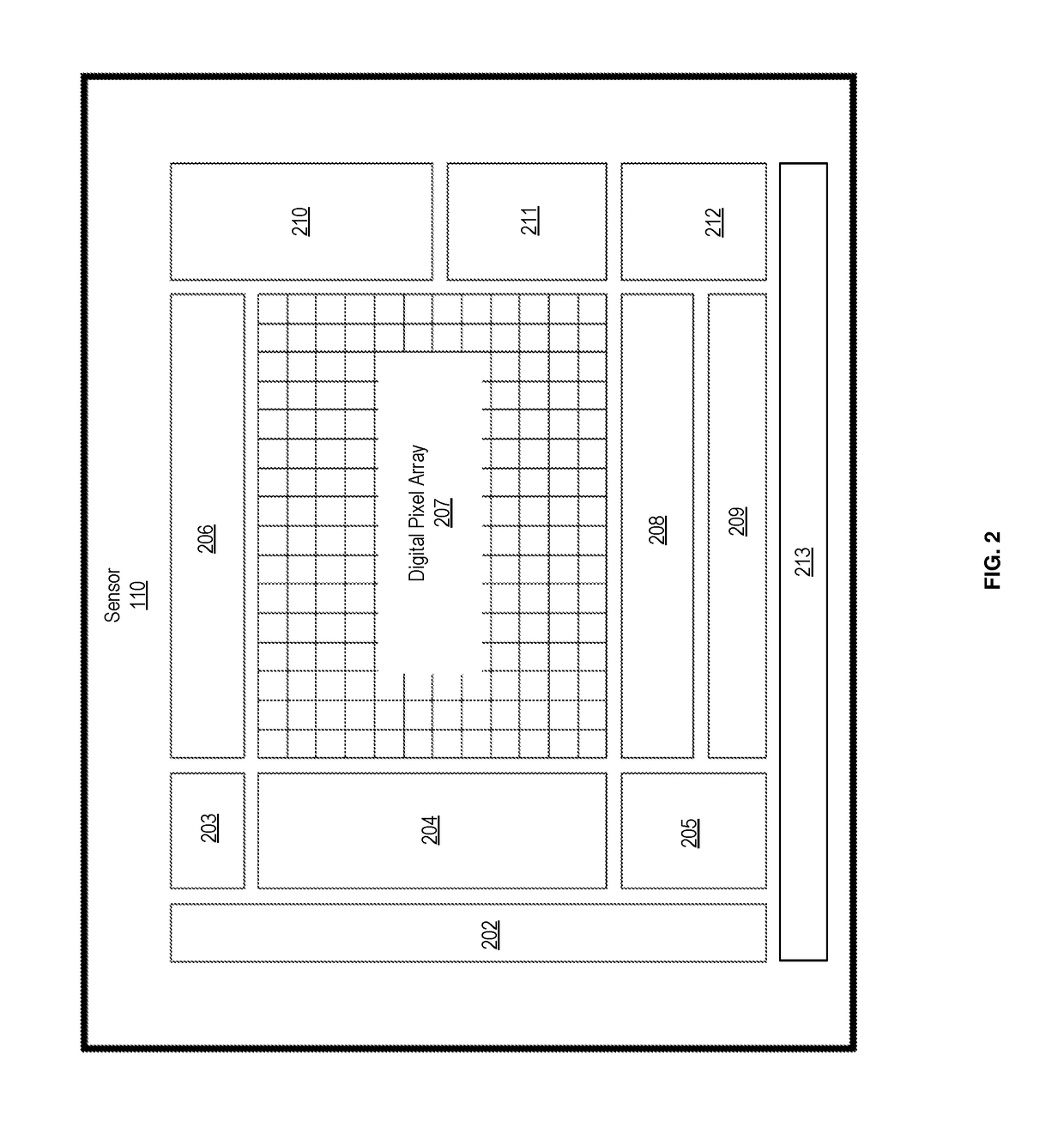
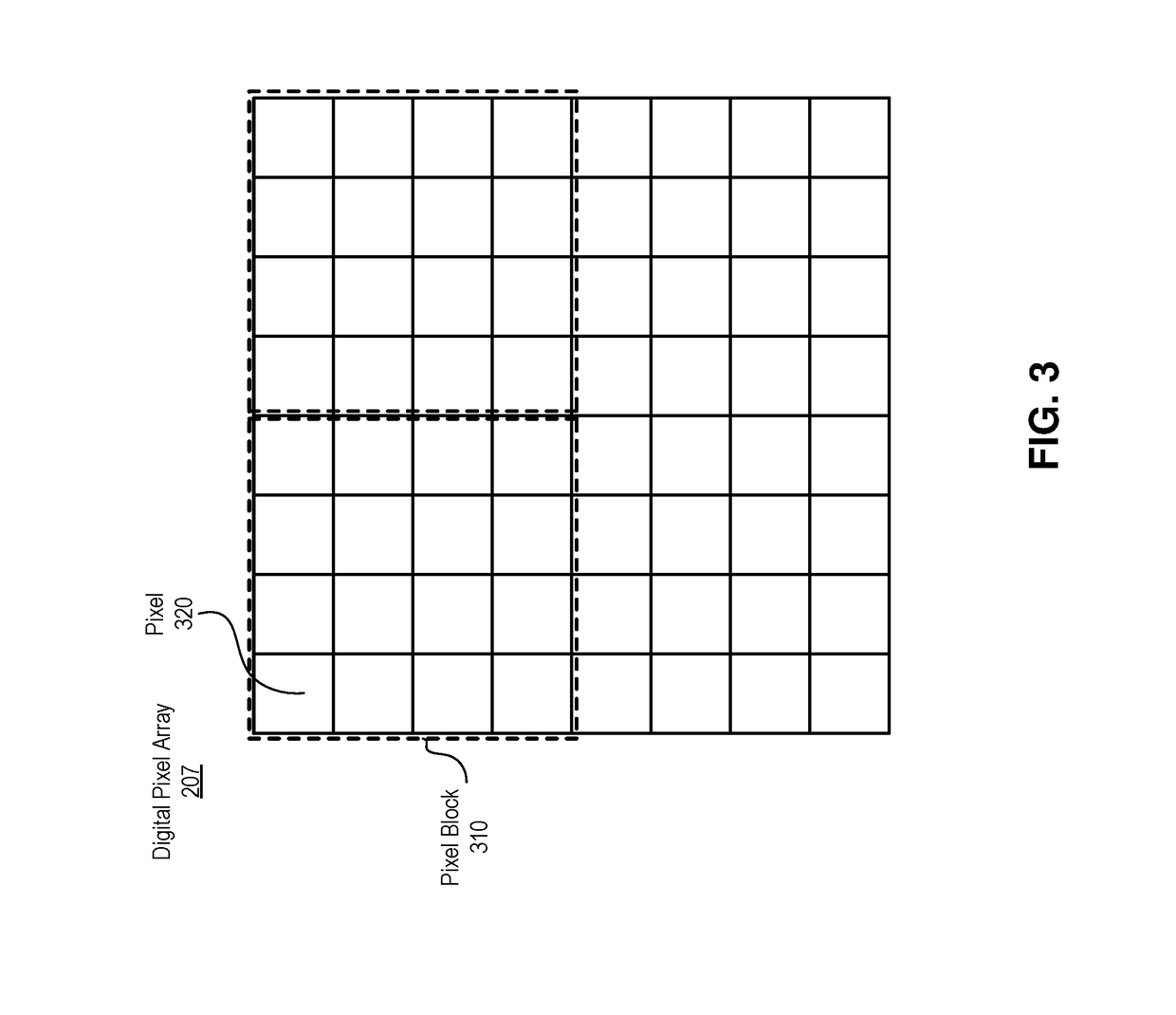
[0056]A block circuit associated with a block of pixels receives and stores 710 exposure time information in a block memory for each block of pixels. The exposure time information includes predicted light intensity information of the current frame for each block indicating a highest light intensity and a lowest light intensity predicted from pixels in each block. The exposure time information also includes an exposure start time and an exposure end time. The exposure time information is provided to the sensor via a MIPI interface circuit with four data lanes.

[0057]A pixel circ...


PUM


Abstract

A photo sensor array is divided up into multiple blocks that are operated with different exposure times. A prediction algorithm is used to predict the overall light brightness of each block and determine the exposure time of each block. Each block may also include memory to store the exposure time for the pixels in the block as well as analog-to-digital resolution for the block.

Description

CROSS REFERENCE TO RELATED APPLICATIONS[0001]This application claims the benefit of U.S. Provisional Application No. 62 / 545,356 filed Aug. 14, 2017, which is incorporated by reference in its entirety.BACKGROUNDField of Technology[0002]This disclosure relates generally to photo sensors, and more particularly, to using a predictive algorithm to adjust exposure times of photo sensors.Discussion of the Related Art[0003]Photo sensors are electronic detectors that convert light into an electronic signal. In photography, a shutter is a device that allows light to pass for a determined period of time, exposing the optical sensors to the light in order to capture an image of a scene. Rolling shutter is a method of image capture in which a still picture or each frame of a video is captured by scanning across the scene rapidly in a horizontal or vertical direction. That is, every pixel is not captured at the same time; pixels from different rows are captured at different times. Rolling shutter...

Claims


Application Information

Patent Timeline
Patent Type & Authority Applications(United States)
IPC IPC(8): H04N5/235H04N5/14H04N5/232H04N5/353H01L25/16
CPCH04N5/2353H04N5/144H04N5/23254H04N5/3535H01L25/167G06T2207/20H04N23/6811H04N23/6812H04N23/73H04N25/531H04N25/533H04N25/79
Inventor LIU, XINQIAO
Owner META PLATFORMS TECH LLC
Why Eureka
Try Eureka