Scraper bar for a scraper blade of a road milling machine

Active Publication Date: 2019-02-21
WIRTGEN GMBH +1
View PDF16 Cites 1 Cited by
  • Summary
  • Abstract
  • Description
  • Claims
  • Application Information

AI Technical Summary

Benefits of technology

[0017]In order to allow the scraper bar to be aligned precisely on the scraper blade in simple fashion, provision can be made that the carrier comprises an extension that projects rearward beyond the rear-side installation surface, such that the installation surface and a support surface of the extension enclose an angle. The scraper bar can be positioned and aligned, with its support surface and the rearward installation surface, o

Problems solved by technology

For example, it is conceivable for a milling bit of the milling drum to sustain damage, in part

Method used


Image

  • Scraper bar for a scraper blade of a road milling machine
  • Scraper bar for a scraper blade of a road milling machine
  • Scraper bar for a scraper blade of a road milling machine

Examples


Embodiment Construction

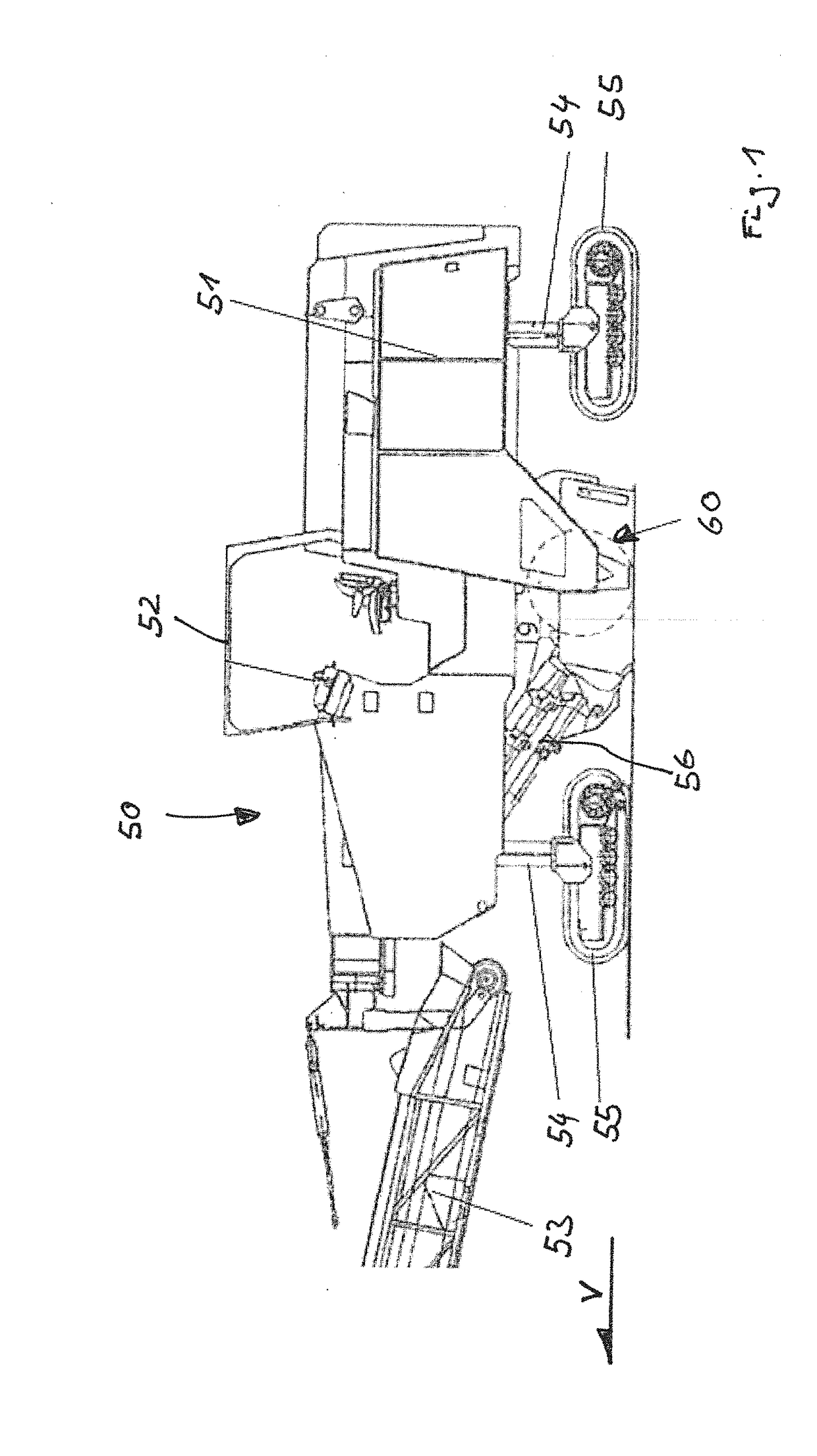
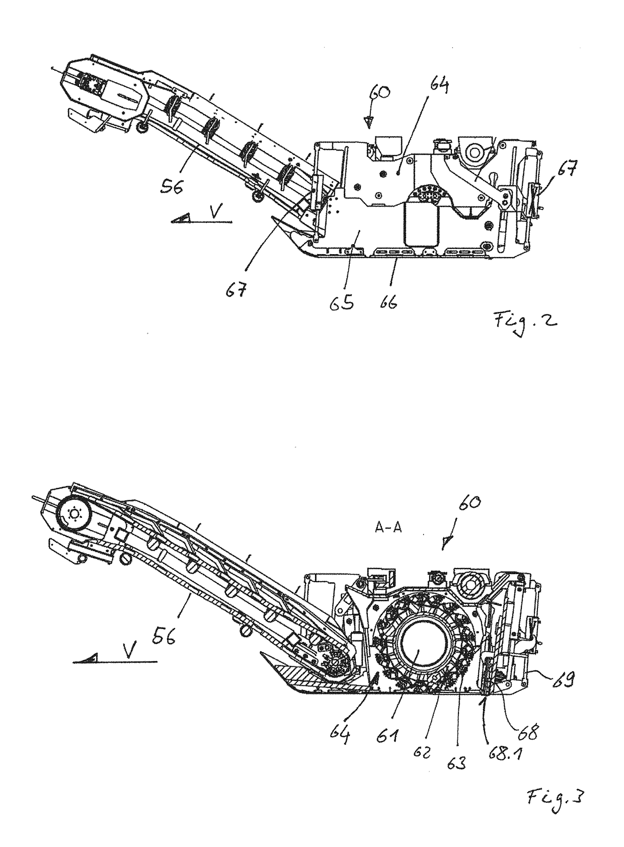
[0030]FIG. 1 is a side view of a road milling machine 50. Road milling machine 50 possesses a chassis 51 that is carried by four propelling units 55. Two front propelling units 55 and two rear propelling units 55 are provided. Each propelling unit 55 is coupled to chassis 51 via a lifting column 54. Chassis 51 can be displaced in height with respect to propelling units 55 via lifting columns 54. Propelling units 55 are embodied in the present case as crawler track units. Chassis 51 furthermore carries a control cabin 52 for a machine operator. Control elements for road milling machine 50 are arranged here so that the machine driver can operate and drive road milling machine 50. A milling unit 60 is arranged between propelling units 55. A receiving belt 56 is associated with milling unit 60. The material milled off by milling unit 60 can be transported away via the receiving belt. Adjacently to receiving belt 56, the milled-off material falls onto a conveyor device 53. Conveyor devic...


PUM


Abstract

The invention relates to a scraper bar (20) for a scraper blade (68) of a road milling machine, having a carrier (10) that comprises a front side and a rearward installation surface (17), the carrier (10) comprising a cutting-element receptacle (13), cutting elements (30) being held, serially arranged along a longitudinal axis (L) extending in a width direction of the carrier (10), on or in the cutting-element receptacle (13), and the cutting elements (30) comprising a cutting edge (35.1) that transitions indirectly or directly into a rake surface (35). In order to improve the working result, provision is made according to the present invention that at least for some of the cutting elements (30), the cutting edge (35.1) is set at least locally not parallel to the longitudinal axis (L).

Description

BACKGROUND OF THE INVENTION1. Field of the Invention[0001]The invention relates to a scraper bar for the scraper blade of a road milling machine.2. Description of the Prior Art[0002]Road milling machines are used in road construction. Their purpose is to remove existing road pavements. The road milling machine possesses, for that purpose, a milling drum that is accommodated in a milling drum housing. The milling drum is populated on its surface with a plurality of milling bits. The milling bits are usually installed in upper parts of quick-change bit holder systems. The quick-change bit holder systems possess a lower part that is mounted on the surface of the milling drum. The upper part is joined replaceably to the lower part. The milling bit is mounted in a receptacle of the upper part.[0003]A rotational motion can be imparted to the milling drum in the milling drum housing. When the drum is set onto the roadway surface, the milling bits mill off the roadway pavement. The milled-o...

Claims


Application Information

Patent Timeline
IPC IPC(8): E01C23/12
CPCE01C23/121E01C23/088E02F3/8152E01C23/127
Inventor BARIMANI, CYRUSLEHNERT, THOMASSALZ, ANDREAS
Owner WIRTGEN GMBH
Why Eureka
Try Eureka