Methods of Manufacturing

a manufacturing method and additive technology, applied in the field of additive manufacturing processes, can solve the problems of part separating from the planned shape, affecting the overall process of building the finished product, and affecting the use effect,

Active Publication Date: 2019-02-21
SIEMENS PROD LIFECYCLE MANAGEMENT SOFTWARE INC
View PDF9 Cites 2 Cited by
  • Summary
  • Abstract
  • Description
  • Claims
  • Application Information

AI Technical Summary

Benefits of technology

[0016]e. increase the range of parts that a given 3-D printer is capable of servicing.

Problems solved by technology

However, in DMLS, and other additive manufacturing techniques, the overall process of building the finished product can be slow and has risks associated product failure and non-conformity, particularly with small batch part production.
Thermal distortion and / or stress accumulation (“thermal effects”), for example, can cause the part to depart from the planned shape, and / or break during usage, as a result of the manufacturing process, if those characteristics of the manufacturing process are not accounted for.
However, when such models are applied to conventional finite element analysis within the conventional computational capacity of production machines, problems can occur.
These problems typically manifest as a slow task completion—it can, for example, take hours for the part optimization to be completed, in given instances even for a single iteration of the analysis.
In general, tying upon a given manufacturing machine, or even a given computer on a specific task for that period of time, is an undesirable risk and a waste of production time.
Further, it is undesirable and often prohibitively expensive for part production to require hours even in completion, much less in the set-up stage for production.

Method used


Image

  • Methods of Manufacturing

Examples


Embodiment Construction

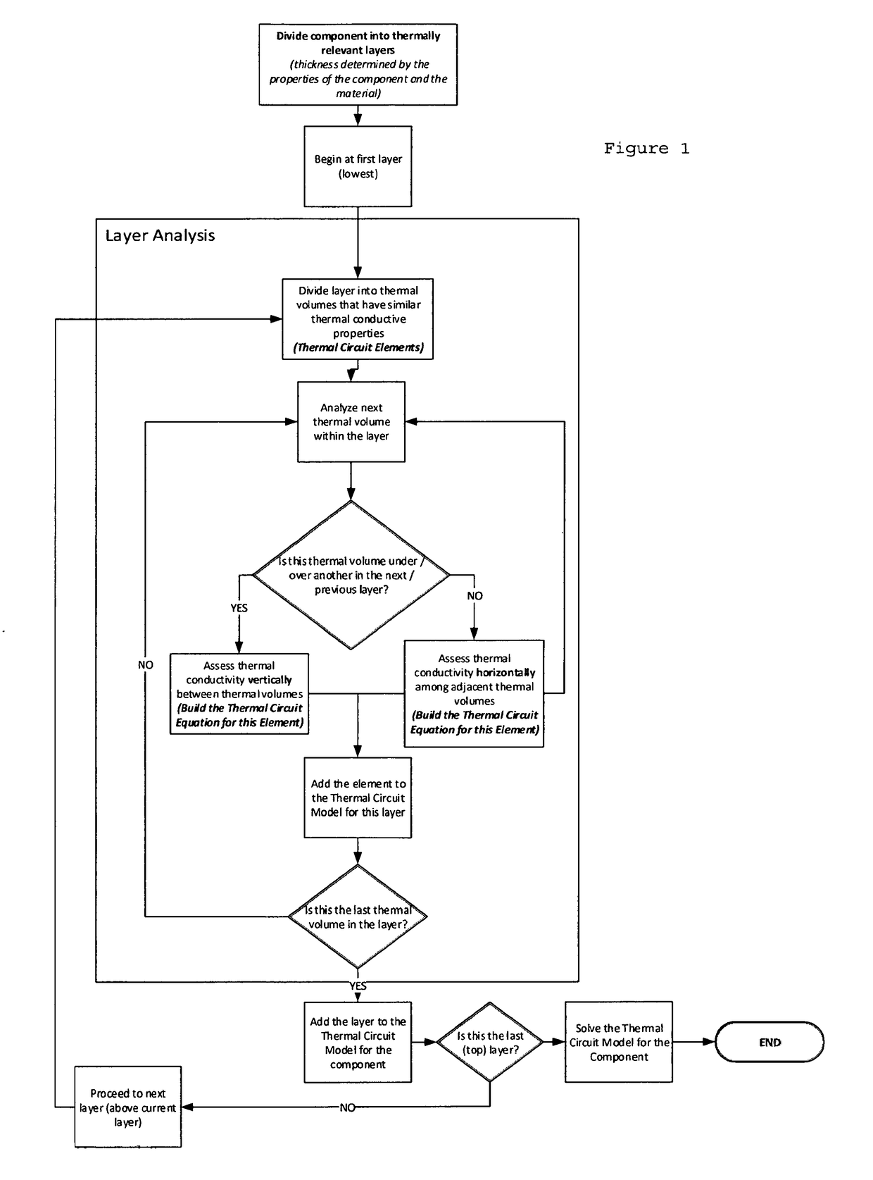
[0020]The present invention has applications for a wide range of additive manufacturing processes, but is particularly useful where finite element analysis techniques are being used in the part optimization portion of the manufacturing process. In general, preferred embodiments of the present invention will follow the four-step process described above, except that the finite element analysis step is streamlined. This allows for substantially less computational power to be required at the part manufacturing site, and faster set-up time.

[0021]The present invention recognizes, for example, that the most significant thermal effects in a part formed from powdered metal typically occur where the boundaries between the thermal volumes being examined by finite element analysis have different characteristics or parameters. For example, this can occur where the metal of a given volume becomes adjacent to a volume of non-metal (such as air). The thermal effects at the boundaries of volumes hav...


PUM

PropertyMeasurementUnit
volumesaaaaaaaaaa
massaaaaaaaaaa
shapeaaaaaaaaaa

Abstract

An improved part optimization process in additive manufacturing is provided, which uses a finite element analysis only where boundary parameter differentiation is detected. For a given part being manufactured, such as in DMLS, thermal effects of adjacent volumes with no boundary parameter differentiation are ignored in the part optimization process. For example, if a given volume is over a volume of the same material, no computational analysis is conducted, but if a volume of metal is over air, then the computational analysis is conducted. This results in significantly less computational time being required. Further, the present invention uses computation equipment remote from the DMLS part production equipments, connected instead via the internet or other such “cloud computing” arrangements.

Description

BACKGROUND OF THE INVENTION[0001]The present invention relates to additive manufacturing processes, and, more particularly, to so-called “3-D” laser printers used in direct metal laser sintering (“DMLS”).[0002]In general, products can be manufactured by several overall methods, including starting with a mass of material, such as a solid block of metal, and then removing portions of that solid block at specific locations to create the desired product shape. This is a common technique with machine tools, such as lathes. Alternatively, (or sometimes additionally), a product can be made by starting with a mass of material, and then pounding, bending, or extruding that mass to create the desired product shape. This is a common technique with stamping presses, for example. In the case of the present invention, however, the manufacturing technique being addressed is where the product shape is created by starting with nothing, and then building layers and layers of material on over or upon ...

Claims


Application Information

Patent Timeline
Patent Type & Authority Applications(United States)
IPC IPC(8): G06T17/20B22F3/105G05B19/4099
CPCG06T17/20B22F3/1055G05B19/4099B22F2003/1057G05B2219/49007B33Y10/00B33Y50/02Y02P10/25B22F10/28B22F10/80
Inventor NEIDIG, JOEL D.PENG, HAO
Owner SIEMENS PROD LIFECYCLE MANAGEMENT SOFTWARE INC
Why Eureka
Try Eureka