Liquid tank

Active Publication Date: 2019-02-28
SEIKO EPSON CORP
View PDF0 Cites 2 Cited by
  • Summary
  • Abstract
  • Description
  • Claims
  • Application Information

AI Technical Summary

Benefits of technology

[0017](10) In the above mode, an opposing wall that is positioned above the liquid outlet, is positioned below a ceiling face of the liquid chamber, and is opposed to at least a portion of the liquid outlet, in the mounted state, may further be provided. According to this mode, it is possible to suppress the height of a wave that is formed in an upper portion of the liquid outlet, using the opposing wall. Accordingly, it is possible to further reduce the likelihood of the liquid outlet coming into contact with air, and thus it is possible to further reduce the likelihood of air bubbles flowing into the liquid ejection head.
[0018](11) In the above mode, the opposing wall may be inclined relative to the horizontal direction in the mounted state. According to this mode, air bubbles generated between the filter member and the opposing wall can be easily released in a direction away from the filter member.
[0019](12) In the above mode, the opposing wall may be connected to the first division walls. According to this mode, it is possible to easily provide the opposing wall whose position is fixed, by connecting the opposing wall to the first division wall.
[0020](13) According to another mode of the invention, a liquid tank that is mounted on a carriage that has a liquid ejection head and can move in a Y direction, and can contain liquid to be supplied to the liquid ejection head is provided. This liquid tank includes a liquid chamber that can contain the liquid, a liquid inlet port through which the liquid can be injected into the liquid chamber, an atmospheric air introduction portion for introducing atmospheric air into the liquid chamber, a liquid outlet provided in a bottom face of the liquid chamber, and an opposing wall that is positioned above the liquid outlet and below a ceiling face of the liquid chamber, and is opposed to at least a portion of the liquid outlet, in a mounted state in which the liquid tank is mounted on the carriage. According to this mode, the liquid tank includes the opposing wall that is positioned below the ceiling face of the liquid chamber, and is opposed to at least a portion of the liquid outlet

Problems solved by technology

Therefore, an ink discharge error may be cau

Method used


Image

  • Liquid tank
  • Liquid tank
  • Liquid tank

Examples


embodiment

A. Embodiment

A-1. Configuration of Liquid Ejection Apparatus

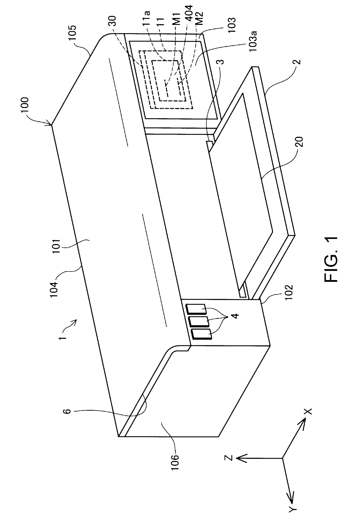
[0057]FIG. 1 is an external view of a liquid ejection apparatus 1 that has a liquid tank 30 as a mode of the invention. FIG. 1 shows three spatial axes orthogonal to each other, namely, an X axis, a Y axis, and a Z axis. A direction along the X axis is referred to as an “X axis direction” (also simply referred to as an “X direction”), a direction along the Y axis is referred to as a “Y axis direction” (also simply referred to as a “Y direction”), and a direction along the Z axis is referred to as a “Z axis direction” (an up-down direction, also simply referred to as a “Z direction”). The liquid ejection apparatus 1 is installed on a plane parallel to the X axis direction and the Y axis direction (an XY plane). A +Z axis direction is the vertically upward direction, and a −Z axis direction is the vertical downward direction. Also in other drawings to be described below, the X axis, Y axis, and Z axis are added as necessary.

[...

first other embodiment

B-1. First Other Embodiment

[0164]The invention is not limited to an inkjet printer and a liquid tank for supplying ink to an inkjet printer, and can also be applied to any liquid ejection apparatus that ejects liquid other than ink and a liquid tank for containing the liquid. For example, the invention can be applied to the following various liquid ejection apparatuses and liquid tanks thereof.

[0165](1) Image recording apparatuses such as a facsimile apparatus,

[0166](2) Color material ejection apparatuses used to manufacture color filters for image display apparatuses such as a liquid crystal display,

[0167](3) Electrode material ejection apparatuses used to form electrodes for organic EL (Electro Luminescence) displays, surface light emission displays (field emission displays, FED), or the like.

[0168](4) Liquid ejection apparatuses that eject liquid containing biological organic matter used to manufacture biochips,

[0169](5) Sample ejection apparatuses serving as precision pipettes,

[...

second other embodiment

B-2. Second Other Embodiment

[0177]In the above embodiment, the entire air second channel 73 serving as an inclined channel of the air communication channel 70 is inclined downward toward the air third channel 74, in the mounted state (FIG. 8), but there is no limitation thereto. For example, only the bottom face of the air second channel 73 may be inclined, in place of the entire air second channel 73. In addition, the air second channel 73 may be inclined upward toward the air third channel 74, in the mounted state. Even in these cases, similar to the embodiment, it is possible to prevent liquid that has flowed into the air second channel 73 from remaining in the air second channel 73. Therefore, it is possible to suppress blockage of the air second channel 73 with liquid that has flowed into the air second channel 73.


PUM


Abstract

Provided is a technique for reducing the likelihood of air bubbles flowing to a liquid ejection head, in a liquid tank mounted on a carriage. The liquid tank mounted on the carriage movable in a Y direction includes a liquid chamber, a liquid inlet port, an atmospheric air introduction portion, a liquid outlet, and a division wall arranged in the liquid chamber. The division wall has first division walls perpendicular to the Y direction in a mounted state on the carriage, and the liquid chamber includes a plurality of small liquid chambers partitioned by the first division walls, an upper communication portion allowing the small liquid chambers to be in communication with each other, and a lower communication portion positioned below the upper communication, and allowing the small liquid chambers to be in communication with each other.

Description

CROSS REFERENCE TO RELATED APPLICATIONS[0001]The present application claims priority from Japanese Patent Application No. 2017-166851 filed on Aug. 31, 2017, the contents of which are hereby incorporated by reference into this application.BACKGROUND1. Technical Field[0002]The present invention relates to a technique of a liquid tank.2. Related Art[0003]Heretofore, there are known techniques in which a wall orthogonal to the direction of reciprocal movement of a carriage (also simply referred to as a “direction of movement”) is provided within a sub tank on the carriage so as to mitigate foaming of ink caused by rippling of the ink liquid surface that accompanies reciprocal movement of the carriage (e.g., JP-4259158).[0004]JP-4259158 is an example of related art.[0005]In previous techniques, when ink flows out from an ink chamber on the downstream side to a head from among two ink chambers partitioned by a wall orthogonal to the direction of movement of a carriage, the ink moves over...

Claims


Application Information

Patent Timeline
IPC IPC(8): B41J2/175
CPCB41J2/17553B41J2/17523B41J2/17513B41J2/17563B41J2/19B41J2/175B41J2/1752B41J2/17596B41J29/13
Inventor SAWADAISHI, MAKOTOKIMURA, NAOMIKUDO, SHOMA
Owner SEIKO EPSON CORP
Why Eureka
Try Eureka