Ultra-small form factor optical connectors using a push-pull boot receptacle release

a technology of optical connectors and push-pull release, applied in the field of ultra-small form factor optical connectors, can solve the problems of obstructing access to individual release mechanisms, reducing service quality, and increasing support costs

Active Publication Date: 2019-02-28
SENKO ADVANCED COMPONENTS
View PDF1 Cites 24 Cited by
  • Summary
  • Abstract
  • Description
  • Claims
  • Application Information

AI Technical Summary

Benefits of technology

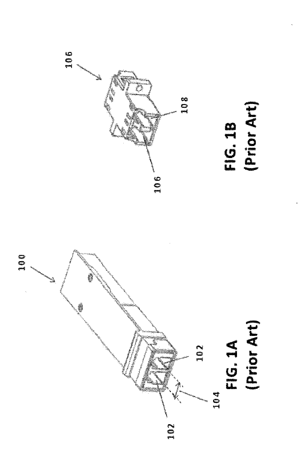
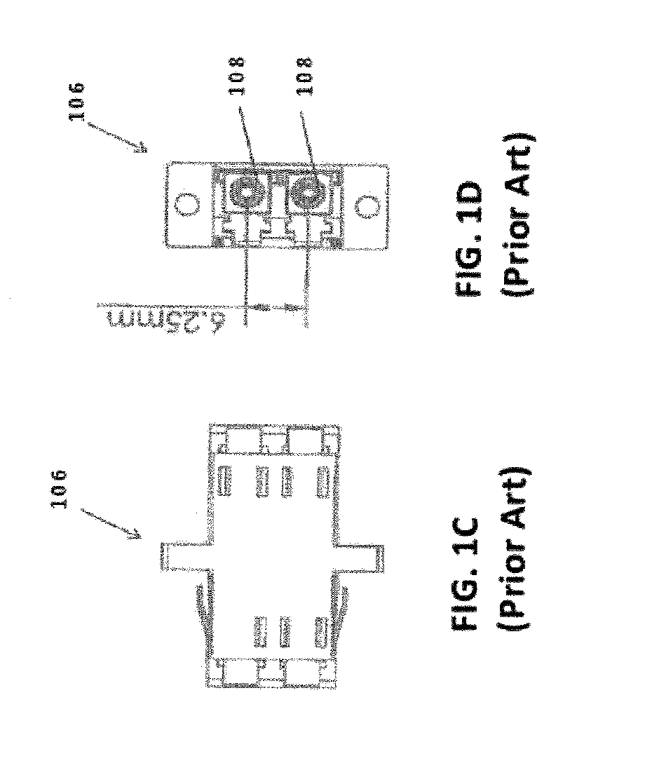
[0008]An optical connector holding two or more LC-type optical ferrules is provided. The optical connector includes an outer body, an inner front body accommodating the two or more LC-type optical ferrules, ferrule springs for urging the optical ferrules towards a mating receptacle, and a back body for supporting the ferrule springs. The outer body and the inner front body are configured such that four LC-type optical ferrules are accommodated in a small form-factor pluggable (SFP) transceiver footprint or eight LC-type optical ferrules are accommodated in a quad small form-factor pluggable (QSFP) transceiver footprint. A mating receptacle (transceiver or adapter) includes a receptacle hook and a housing with an opening that accommodates the receptacle hook in a flexed position as the optical connector makes connection with the mating receptacle by introducing the receptacle hook into an optical receptacle hook recess.
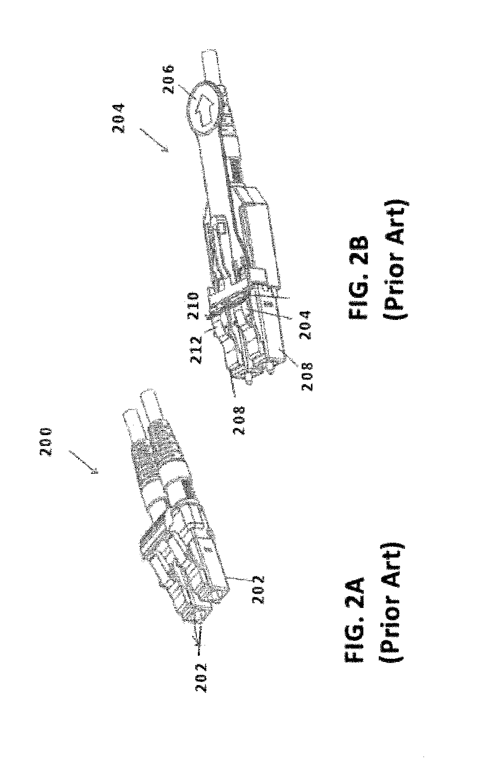
[0009]Optical connector disclosed herein is released from a receptacle using a boot release. The boot release is integrated with fiber cable. The boot release is configured with one or more outer wings or protrusions received in an opening of connector outer housing at a distal end of connector. The protrusions limit travel of connector to ensure receptacle hook is displaced from front body recess so connector can be removed from receptacle opening.

Problems solved by technology

While both approaches may be effective to increase the panel connector density, shrinking the connector size and / or spacing may also increase the support cost and diminish the quality of service.
In a high-density panel configuration, adjacent connectors and cable assemblies may obstruct access to the individual release mechanisms.
Such physical obstructions may impede the ability of an operator to minimize the stresses applied to the cables and the connectors.
Overstressing the cables and connectors may produce latent defects, compromise the integrity and / or reliability of the terminations, and potentially cause serious disruptions to network performance.
While an operator may attempt to use a tool, such as a screwdriver, to reach into a dense group of connectors and activate a release mechanism, adjacent cables and connectors may obstruct the operator's line of sight, making it difficult to guide the tool to the release mechanism without pushing aside the adjacent cables.
Moreover, even when the operator has a clear line of sight, guiding the tool to the release mechanism may be a time-consuming process.
Thus, using a tool may not be effective at reducing support time and increasing the quality of service.

Method used


Image

  • Ultra-small form factor optical connectors using a push-pull boot receptacle release
  • Ultra-small form factor optical connectors using a push-pull boot receptacle release
  • Ultra-small form factor optical connectors using a push-pull boot receptacle release

Examples


Embodiment Construction

[0089]This disclosure is not limited to the particular systems, devices and methods described, as these may vary. The terminology used in the description is for the purpose of describing the particular versions or embodiments only, and is not intended to limit the scope.

[0090]As used in this document, the singular forms “a,”“an,” and “the” include plural references unless the context clearly dictates otherwise. Unless defined otherwise, all technical and scientific terms used herein have the same meanings as commonly understood by one of ordinary skill in the art. Nothing in this disclosure is to be construed as an admission that the embodiments described in this disclosure are not entitled to antedate such disclosure by virtue of prior invention. As used in this document, the term “comprising” means “including, but not limited to.”

[0091]The following terms shall have, for the purposes of this application, the respective meanings set forth below.

[0092]A connector, as used herein, re...


PUM


Abstract

An optical connector holding two or more LC-type optical ferrules is provided. The optical connector includes an outer body, an inner front body accommodating the two or more LC-type optical ferrules, ferrule springs for urging the optical ferrules towards a mating receptacle, and a back body for supporting the ferrule springs. The outer body and the inner front body are configured such that four LC-type optical ferrules are accommodated in a small form-factor pluggable (SFP) transceiver footprint or eight LC-type optical ferrules are accommodated in a quad small form-factor pluggable (QSFP) transceiver footprint. A connector is released by pulling distally on boot assembly until receptacle hook is displaced from receptacle hook recess at a proximal end of connector.

Description

CROSS-REFERENCE TO RELATED APPLICATIONS[0001]This application is a continuation-in-part and claims priority to U.S Provisional Patent Application Ser. Nos. 62 / 549,655 filed Aug. 24, 2017, and 62 / 588,276 filed Nov. 17, 2018, the disclosures of which are incorporated by reference herein.FIELD OF THE INVENTION[0002]The present disclosure relates generally to ultra-small form factor optical connectors and related connections within adapters and optical transceivers.BACKGROUND[0003]The prevalence of the Internet has led to unprecedented growth in communication networks. Consumer demand for service and increased competition has caused network providers to continuously find ways to improve quality of service while reducing cost.[0004]Certain solutions have included deployment of high-density interconnect panels. High-density interconnect panels may be designed to consolidate the increasing volume of interconnections necessary to support the fast-growing networks into a compacted form facto...

Claims


Application Information

Patent Timeline
Patent Type & Authority Applications(United States)
IPC IPC(8): G02B6/38G02B6/42
CPCG02B6/387G02B6/3825G02B6/3893G02B6/3887G02B6/4292G02B6/3821G02B6/3879G02B6/38875G02B6/403G02B6/406
Inventor CHANG, JIMMY JUN-FUTAKANO, KAZUYOSHI
Owner SENKO ADVANCED COMPONENTS
Why Eureka
Try Eureka