
Sealing device for a hub/wheel assembly and hub/wheel assembly having such a sealing device

a sealing device and hub/wheel technology, which is applied in the direction of roller bearings, mechanical devices, transportation and packaging, etc., can solve the problems of poor use of adhesive materials and detriment of production times

Active Publication Date: 2019-03-07
AB SKF
View PDF0 Cites 2 Cited by
  • Summary
  • Abstract
  • Description
  • Claims
  • Application Information

AI Technical Summary

Benefits of technology

The present invention aims to produce a sealing device for a hub / wheel assembly that does not have the abovementioned disadvantages. The sealing device includes a guard, a snap-engagement tooth, and an annular gasket. The guard seals off the bearing and has a cylindrical mounting wall with a snap-engagement tooth that snaps into a contoured annular groove in the collar of the outer ring. The annular gasket is made of thermoplastic elastomer and is co-injection-molded inside the gripping seat of the cylindrical mounting wall. The gripping seat has a curved surface that allows for radial deformation of the cylindrical mounting wall until the snap-engagement tooth is snapped into the contoured annular groove. The annular gasket has rounded protuberances and a hollow defined axially by the two protuberances. The snap-engagement tooth can be continuous or discrete. The technical effects of this invention are improved sealing, reduced friction, and improved durability of the hub / wheel assembly.

Problems solved by technology

However, the use of this adhesive material is not particularly good from the environmental viewpoint, and moreover requires considerable precautions during the assembly of the sealing devices, to the detriment of production times.

Method used


Image

  • Sealing device for a hub/wheel assembly and hub/wheel assembly having such a sealing device
  • Sealing device for a hub/wheel assembly and hub/wheel assembly having such a sealing device
  • Sealing device for a hub/wheel assembly and hub/wheel assembly having such a sealing device

Examples


Embodiment Construction

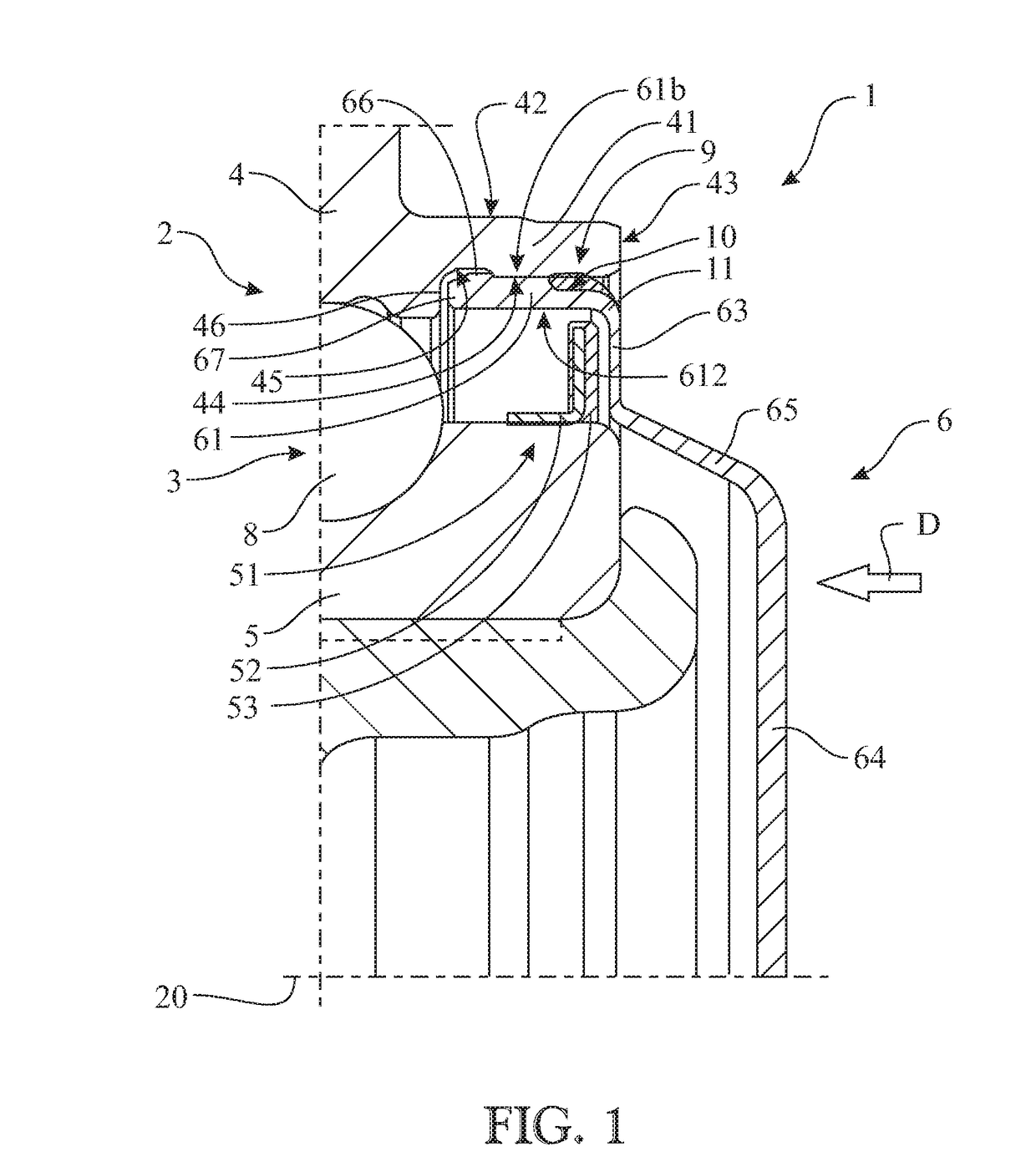
[0027]With reference to FIG. 1, a sealing device for a hub / wheel assembly 2 is shown with the general reference sign 1.

[0028]The assembly 2 has a roller bearing 3 comprising an outer ring 4, coaxial with an axis A of rotation of the bearing 3, an inner ring 5 coaxial with the outer ring 4, and a plurality of roller elements 8, for example balls, interposed between the outer ring 4 and the inner ring 5 to allow the inner ring 5 to rotate, in rotational use, with respect to the outer ring 4, in fixed use. The outer ring 4 of the bearing 3 has a collar 41, which is defined by a cylindrical outer lateral surface 42, an annular end surface 43, and a cylindrical inner lateral surface 44. As for the inner ring 5, the inner ring 5 has a phonic wheel 51, which is rigidly secured to the inner ring 5 and has a mounting support 52 defined, preferably, by a plate bent in the shape of an L, and a ring 53 of ferromagnetic material fastened to the support 52.

[0029]The sealing device 1, according to...


PUM

PropertyMeasurementUnit
axial distanceaaaaaaaaaa
radial thicknessaaaaaaaaaa
axis of symmetryaaaaaaaaaa

Abstract

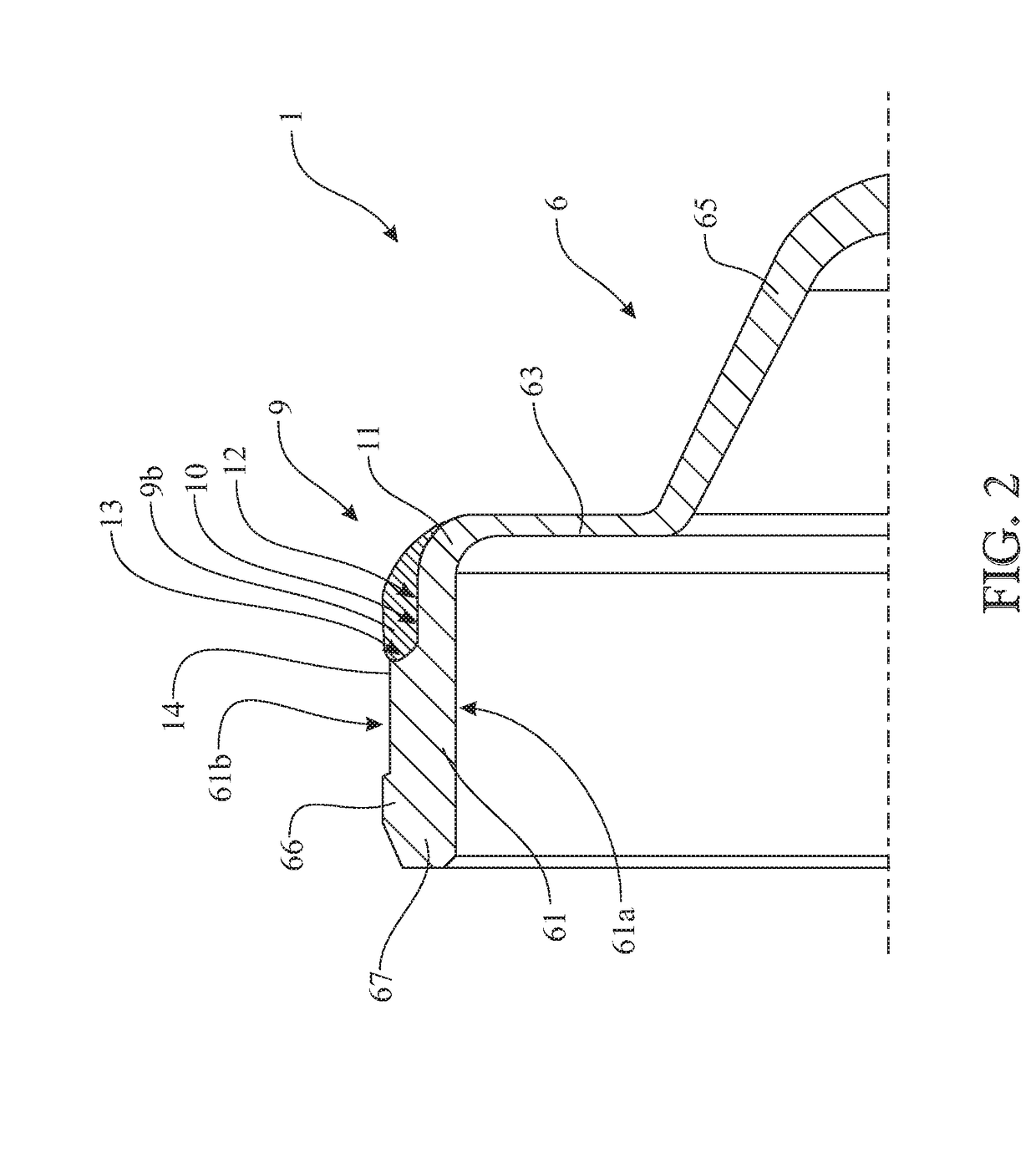
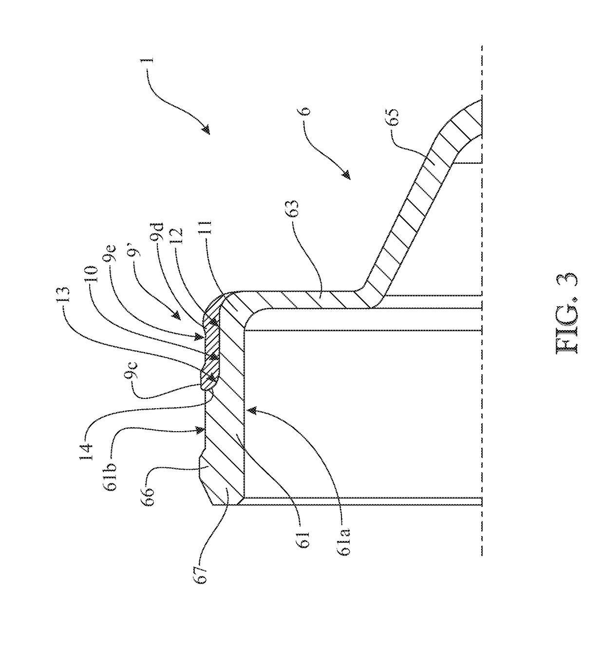
A sealing device for a hub / wheel assembly with a roller bearing, the sealing device comprising a guard, made of plastic, which is coupled to an outer ring of the bearing so as to seal off the bearing, and which has a cylindrical mounting wall having an outer lateral surface coupled to an inner lateral surface of a collar of the outer ring. The sealing device includes a snap-engagement tooth for engaging with the collar made along the outer lateral surface so that the snap-engagement tooth snap-fits in a contoured annular groove made along the collar about the axis and an annular gasket made of thermoplastic elastomer being co-injection-molded inside a gripping seat made in the cylindrical mounting wall on the same side as the snap-engagement tooth, substantially at a corner defined between the cylindrical mounting wall and an annular reading wall transverse to the cylindrical mounting wall.

Description

CROSS-REFERENCE[0001]This application claims priority to Italian patent application no. 102017000099285 filed on Sep. 5, 2017, the contents of which are fully incorporated herein by reference.TECHNOLOGICAL FIELD[0002]The present invention relates to a sealing device for a hub / wheel assembly. The invention also relates to a bearing / hub assembly having such a sealing device.[0003]The present invention is particularly, although not exclusively, applicable to the field of hub / wheel assemblies for motor vehicles having a roller bearing for a non-driving wheel. In such applications, the inner ring of the bearing is rigidly secured to the shaft of the wheel and transmits to the latter the consequent rotary movement, while the outer ring of the bearing is rigidly secured to a fixed hub, for example a hub of a motor vehicle suspension. The text below will refer, by way of example, to this specific use, although it remains generally applicable.BACKGROUND[0004]Since the invention applies in th...

Claims


Application Information

Patent Timeline
Patent Type & Authority Applications(United States)
IPC IPC(8): B60B27/00B60B27/02F16C19/38F16C33/78
CPCB60B27/0073B60B27/0005B60B27/02F16C19/38F16C33/78B60B2380/12B60B2900/5112B60B2900/5114B60B2310/204B60B2360/3412B60B2320/10F16C2326/02F16C33/7816F16C33/7873F16C2326/10F16C2226/74F16C33/723F16C33/7843F16C33/7886F16C41/007F16C19/186F16C33/586
Inventor FALOSSI, MARCOBERTOLA, MAURIZIOMISSIAGGIA, GIORGIO
Owner AB SKF
Learn More