
Impact Energy Absorbing Structure

a technology of energy absorption and structure, applied in the direction of bumpers, vehicle components, understructures, etc., can solve the problems of unsafe driving of vehicles with deformed chassis and high repair costs, and achieve the effects of convenient manufacture, convenient ‘tune-in, and easy replacemen

Active Publication Date: 2019-03-14
GORDON MURRAY DESIGN
View PDF5 Cites 4 Cited by
  • Summary
  • Abstract
  • Description
  • Claims
  • Application Information

AI Technical Summary

Benefits of technology

The invention relates to a crush box which can be easily manufactured and attached to a vehicle structure or chassis. The crush box has a predetermined deformation behavior and can absorb impact energy in a controlled and precise manner. The deformation behavior can be adjusted as needed for different applications. The crush box has a constant wall thickness throughout, which minimizes the amount of material used and allows for a lightweight design. The passageways have the same shape and size, which simplifies the calculation of the crush box's deformation and energy absorbing characteristics. The invention helps to avoid unnecessary repair or replacement of the entire vehicle chassis and maximizes safety in the event of an impact or crash.

Problems solved by technology

In the case of a severe impact, the energy transferred to the chassis can be sufficient to deform the chassis; whilst this is helpful in protecting the vehicle occupants, a vehicle with a deformed chassis will be unsafe to drive and expensive to repair.

Method used


Image

  • Impact Energy Absorbing Structure
  • Impact Energy Absorbing Structure

Examples


Embodiment Construction

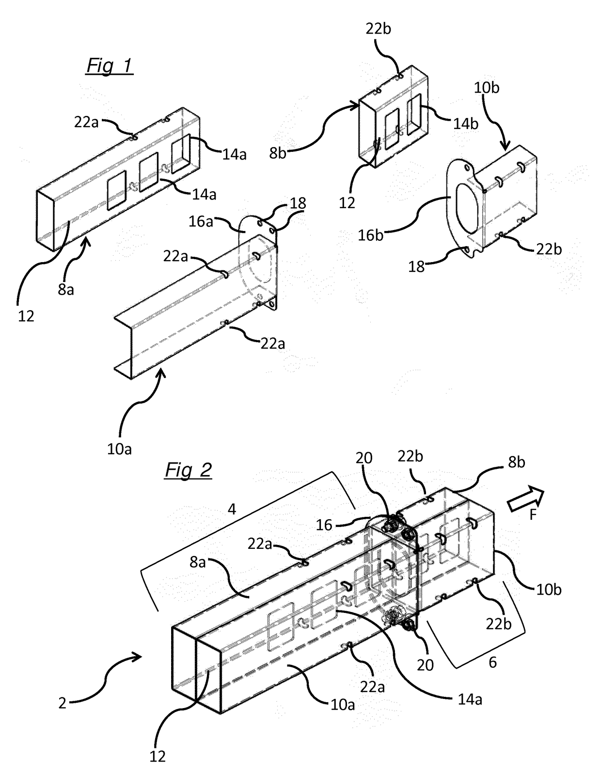
[0016]Referring to FIGS. 1 and 2, these show a crash rail, or longitudinally compressible energy absorbing member for a vehicle, 2 intended to be mounted to the vehicle structure or chassis (not shown) so as to point in the general direction of vehicle forward motion as indicated by arrow F in FIG. 2, and the terms “forward” and “rearward” used herein should be construed accordingly (we prefer to mount the crash rails in parallel with the direction of vehicle forward motion, but it may be advantageous in some applications to orient the crash rail at an angle, vertical and / or horizontal, to this direction). The drawings illustrate the principles of the present invention, but do not show the extreme ends of the crash rail and how these are to be mounted to the vehicle structure or chassis at one end and to the bumper at the other, since this is a straightforward design matter. The crash rail comprises a rearward, high impact energy absorbing portion 4, the elements of which are shown ...


PUM


Abstract

An axially compressible energy absorbing member for a vehicle comprising a thin-walled tube having at least two adjacent, substantially parallel, axially-extending passageways defined by tube walls and separated where they are adjacent by a wall section, wherein the wall section includes one or more apertures of predetermined shape(s) and / or size(s), and wherein the thickness of the tube walls and of the wall section is substantially constant and the same.

Description

FIELD OF THE INVENTION[0001]The present invention relates to an impact energy absorbing or crash structure for a vehicle, particularly but not exclusively an automotive vehicle such as a car.BACKGROUND ART[0002]It is known to provide cars with structures which absorb the energy caused by an impact or crash in order to protect the occupants of the vehicle; many such structures absorb energy by deforming under the force of an impact. One such structure is a vehicle bumper, or fender. These are mounted at the front and rear of the vehicle, and attached to the vehicle chassis; they absorb the energy of a frontal (or rear) impact, and absorb some energy through deforming and transfer the remainder of the energy to the vehicle chassis. In the case of a severe impact, the energy transferred to the chassis can be sufficient to deform the chassis; whilst this is helpful in protecting the vehicle occupants, a vehicle with a deformed chassis will be unsafe to drive and expensive to repair. Acc...

Claims


Application Information

Patent Timeline
Patent Type & Authority Applications(United States)
IPC IPC(8): B60R19/34
CPCB60R19/34B62D21/15
Inventor COPPUCK, FRANK
Owner GORDON MURRAY DESIGN
Learn More