Screening device

a screening device and grating technology, applied in the direction of water/sludge/sewage treatment, filtration separation, stationary filter element filters, etc., can solve the problems of limited screen surface of sewers, and reduced efficiency of screening devices, so as to improve the efficiency of screening and reduce the amount of contaminants that can be separated, the effect of rapid and economic repair

Active Publication Date: 2019-03-21
HUBER SE
View PDF0 Cites 7 Cited by
  • Summary
  • Abstract
  • Description
  • Claims
  • Application Information

AI Technical Summary

Benefits of technology

[0024]It is further advantageous when the sieve grate has an essentially U-shape or V-shape as viewed at the inlet opening, i.e., in the flow direction of the wastewater flowing into the screening device. The sieve grate extends at least partially along the closed loop path of the drive means. Therefore, the clearing elements guided on this closed loop path can be guided along the sieve grate and can remove the contaminants. Moreover, the effectively usable surface of the sieve grate can be configured to be relatively large in a structurally simple way. For the rest, the legs of the U-shape or V-shape can be equally long. It is also conceivable that the aforementioned legs extend in parallel. Preferably, the horizontal spacing between the legs increases in the vertical direction upward, however.
[002

Problems solved by technology

It is disadvantageous, however, that the throughput capacity and, therefore, the efficiency of the screening device decrease as a resu

Method used


Image

  • Screening device
  • Screening device
  • Screening device

Examples


Embodiment Construction

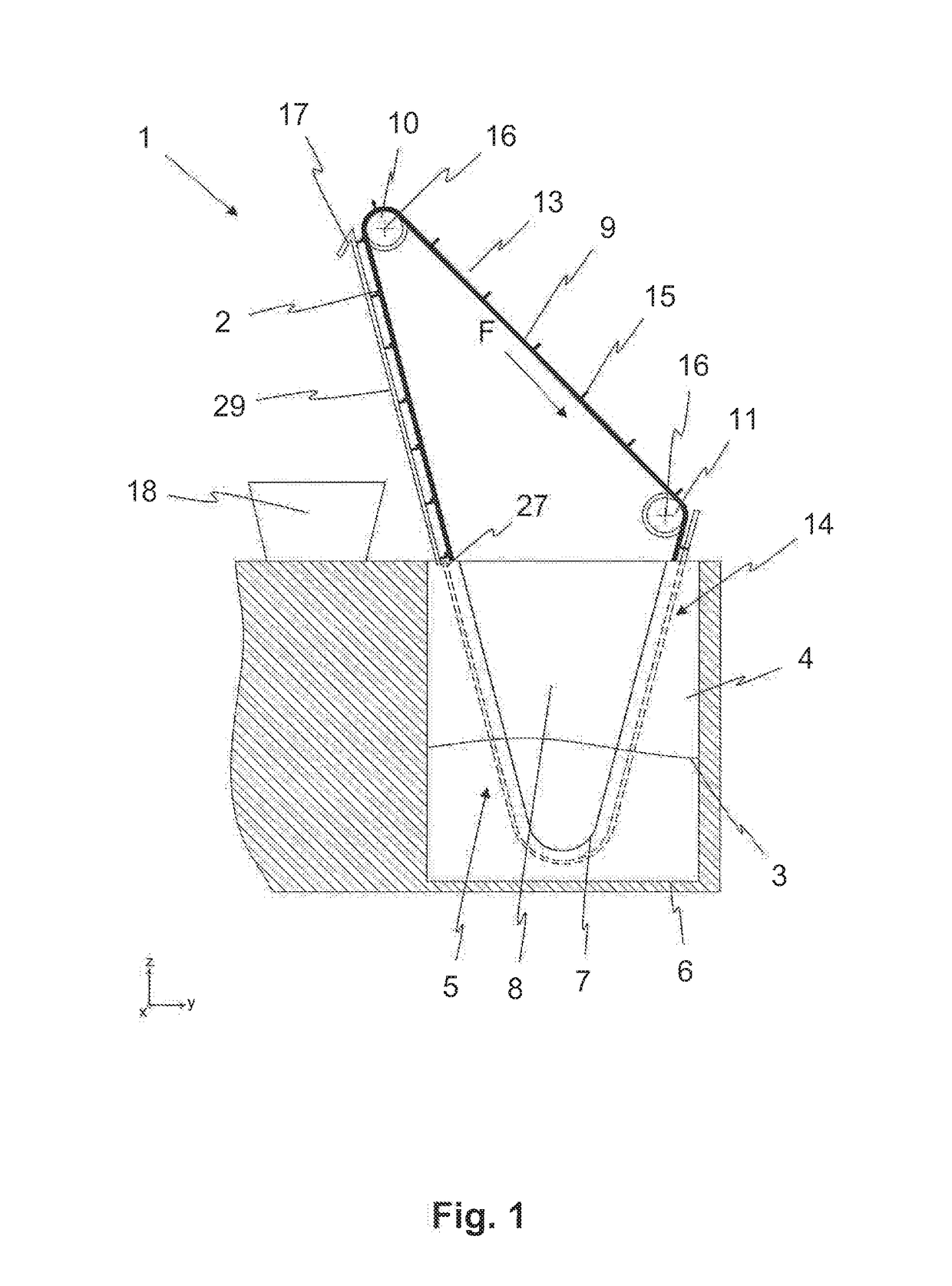
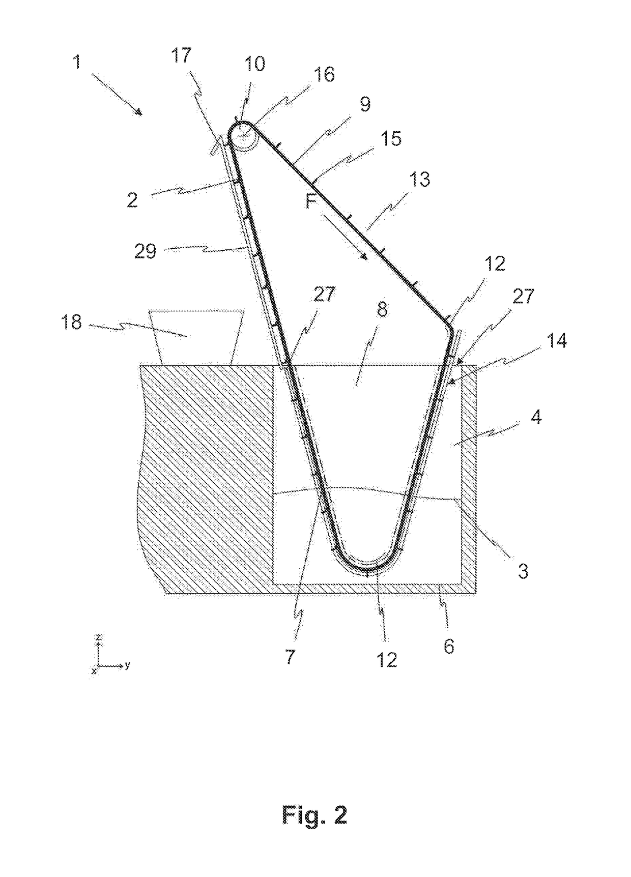
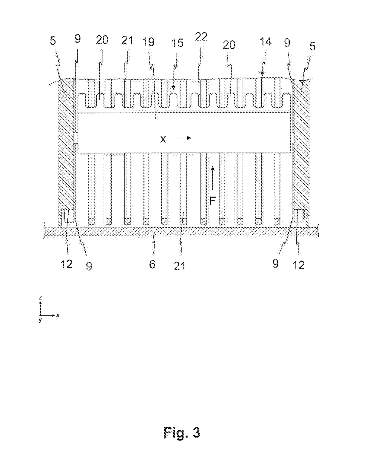
[0038]FIGS. 1 and 2 each show a screening device 1 for separating out and removing contaminants 2, in particular, screenings, from wastewater 3. The screening device 1 is integrated into a sewer 4 and comprises a frame 5, via which the screening device 1 is anchored in the sewer 4. As shown in FIGS. 3 and 4, the frame 5 is connected, for example, to a channel bed 6 of the sewer 4 by way of fastening elements (not shown).

[0039]The wastewater 3 can flow into the screening device 1 through the inlet opening 7 defined by the frame 5 at the entrance in the front of the screening device 1. The section of the screening device 1 forming the inlet opening 7 is not shown in FIG. 2, in order to be able to show the sections located therebehind (the inlet opening 7 located in front of the sheet plane is represented by a dashed line). Essentially, however, the section is a wall of the frame 5, which extends in parallel to the sheet plane and is sealingly closed off by the channel bed 6 and the la...


PUM

PropertyMeasurementUnit
Pressureaaaaaaaaaa
Flow rateaaaaaaaaaa
Shapeaaaaaaaaaa

Abstract

A screening device for separating out and removing contaminants from wastewater includes two continuous conveyors, which are mounted with clearance from each other. Each has a drive wheel that is guided on a circular path and includes a fixedly situated bar screen, which includes multiple mutually spaced grating bars for removing contaminants from the wastewater. Each bar screen includes multiple clearing elements, which are connected to the conveyor for removing from the bar screen the contaminants that have been separated out by the bar screen. The bar screen forms a fixed screen surface that extends, in the intended installation position of the screening device, essentially in the flow direction of the wastewater reaching the screening device.

Description

CROSS-REFERENCE TO RELATED APPLICATIONS[0001]This application claims priority to International Application Serial No. PCT / EP2017 / 053609, filed Feb. 17, 2017, which claims priority to German Application No. 10 2016 103 081.3, filed Feb. 23, 2016. International Application Serial No. PCT / EP2017 / 053609 is hereby incorporated herein in its entirety for all purposes by this reference.FIELD OF THE INVENTION[0002]The present invention relates to a screening device for separating out and removing contaminants from wastewater, comprising two continuous drive means which are mounted with clearance from each other, wherein the drive means are guided on a circular path with the aid of at least one drive wheel in each case, comprising a fixedly situated sieve grate which includes multiple mutually spaced grating bars for separating contaminants from the wastewater, and comprising multiple clearing elements, which are connected to the drive means, for removing the contaminants, which have been se...

Claims


Application Information

Patent Timeline
IPC IPC(8): E03F5/14B01D29/35B01D29/44B01D29/64
CPCE03F5/14B01D29/35B01D29/445B01D29/6484E02B8/026
Inventor ABT, SIMON
Owner HUBER SE
Why Eureka
Try Eureka