Gas sensor

Active Publication Date: 2019-03-21
NGK SPARK PLUG CO LTD
View PDF2 Cites 2 Cited by
  • Summary
  • Abstract
  • Description
  • Claims
  • Application Information

AI Technical Summary

Benefits of technology

[0010]Some types of sensor elements are known including not only a thermal conductivity type sensor element but also a contact combustion type sensor element that causes combustion of hydrogen gas by the action of a combustion catalyst such as noble metal. In the high hydrogen gas concentration environment, there is a possibility of oxygen depletion. When combustion contact type sensor elements are used as the first and second sensor elements, the current detected by the current detecting portion may become small due to less combustion reaction of hydrogen gas

Problems solved by technology

Although the membrane member has the property of not allowing permeation of hydrogen gas as mentioned above, it is not possible to completely in

Method used


Image

  • Gas sensor
  • Gas sensor
  • Gas sensor

Examples


embodiment

1-1. Embodiment

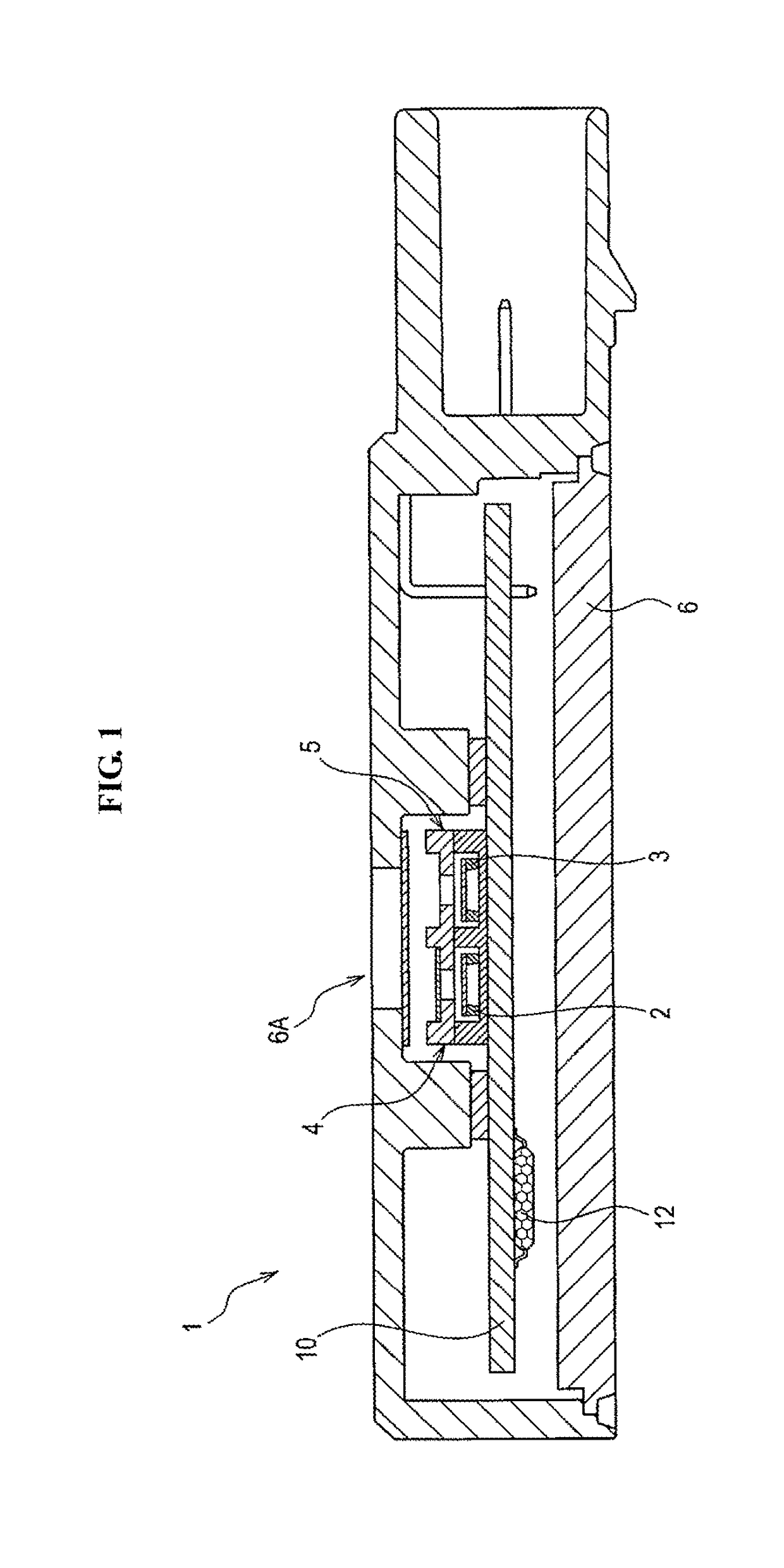
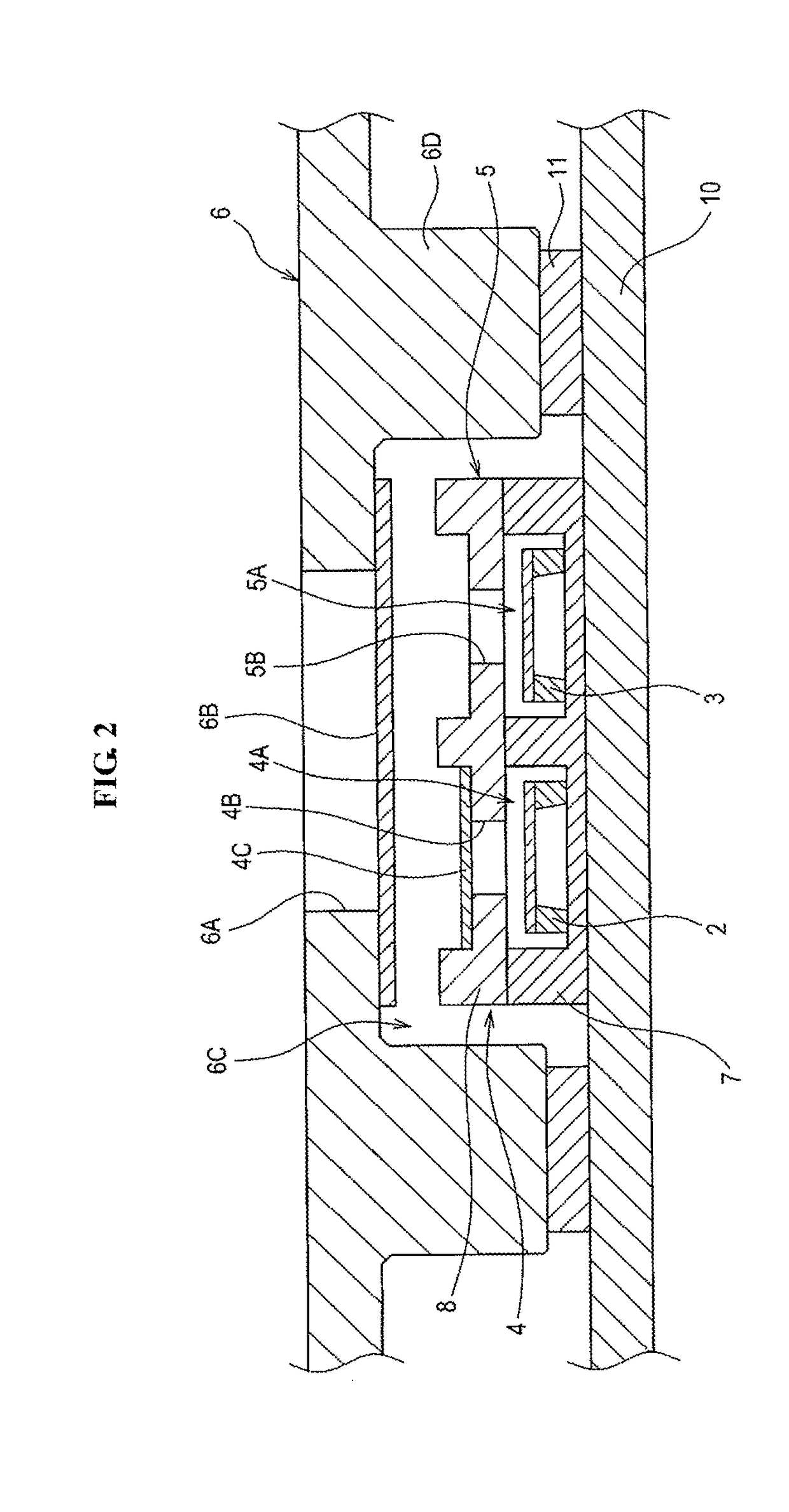
[0020]A gas sensor 1 according to one embodiment of the present invention is used to detect and measure hydrogen gas in a measurement gas atmosphere. As shown in FIGS. 1 and 2, the gas sensor 1 includes a first sensor element 2, a second sensor element 3, a first installation part 4, a second installation part 5, a casing 6, a circuit board 10 and a calculation unit 12.

[0021]

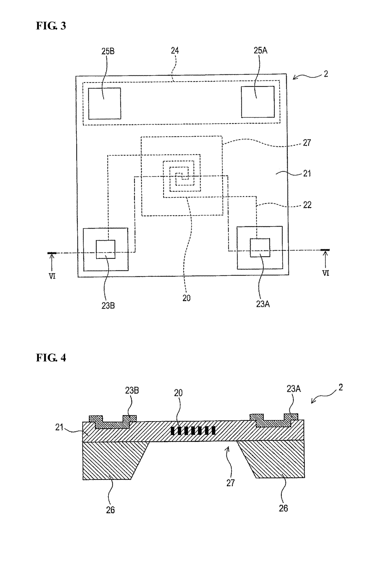
[0022]The first sensor element 2 is in the form of a thermal conductivity type sensor element having a heating resistor 20 whose resistance value varies with changes in temperature thereof. More specifically, the first sensor element 2 includes a heating resistor 20, an insulating layer 21, a wiring 22, a pair of first electrode pads 23A and 23B, a temperature measuring resistor 24, a pair of second electrode pads 25A and 25B and a substrate 26 as shown in FIGS. 3 and 4.

[0023]The heating resistor 20 is provided as a spiral pattern conductor and is embedded in a center portion of the insulating lay...

modification examples

2. Modification Examples

[0078]Although the present invention has been described with reference to the above embodiment, the above embodiment is intended to facilitate understanding of the present invention and is not intended to limit the present invention thereto. Various changes and modifications can be made to the above embodiment without departing from the scope of the present invention.

[0079](2a) The calculation unit 12 does not necessarily make

After the lapse of the predetermined time from the start of voltage application to the first and second sensor elements 2 and 3. A shown in FIG. 7, it is feasible to perform the processing of steps S30 to 70 (the calculation of the hydrogen gas concentration D and the judgment about the presence of the hydrogen gas at high concentration) immediately after the actuation of the calculation unit 12 in step S10.

[0080](2b) The above-mentioned structures of the first and second installation parts 4 and 5 are merely an example. The first and se...


PUM


Abstract

Disclosed is a gas sensor for detecting hydrogen gas in a measurement gas atmosphere, including: a first installation part defining a first inner space in communication with the measurement gas atmosphere through a solid electrolyte membrane member; a second installation part defining a second inner space in direct communication with the measurement gas atmosphere; first and second sensor elements respectively installed in the first and second inner spaces; and a calculation unit configured to calculate the concentration of the hydrogen gas according to a potential between the first and second sensor elements. The gas sensor further includes a current detecting portion that detects a current flowing through the first and second sensor elements. The calculation unit is configured to, when the current detected by the current detecting portion is larger than or equal to a threshold value, judge that the hydrogen gas is present at high concentration.

Description

FIELD OF THE INVENTION[0001]The present invention relates to a gas sensor.BACKGROUND OF THE INVENTION[0002]There is known a gas sensor capable of detecting and measuring hydrogen gas in a measurement gas atmosphere without being influenced by water (humidity) as in, for example, Japanese Laid-Open Patent Publication No. 2001-124716. This gas sensor has a pair of first and second sensor elements installed in first and second separate inner spaces. The first inner space in which the first sensor element (as a reference sensor element) is installed is in communication with the measurement gas atmosphere through a membrane member, whereas the second inner space in which the second sensor element (as a detection sensor element) is installed is open to the measurement gas atmosphere. The membrane member has the property of allowing permeation of water vapor but not allowing permeation of hydrogen gas (as a measurement target gas). In this configuration, both of the first and second sensor...

Claims


Application Information

Patent Timeline
IPC IPC(8): G01N27/18G01N27/12G01N27/407G01N25/18G01N33/00
CPCG01N27/18G01N27/12G01N27/407G01N25/18G01N33/005G01N27/4071G01N27/4074G01N27/4077G01N27/4078G01N33/006
Inventor YAMASHITA, MASAHIROKITANOYA, SHOJIWATANABE, MASAYAMATSUKURA, YUSUKEICHIKAWA, DAISUKE
Owner NGK SPARK PLUG CO LTD
Why Eureka
Try Eureka