Intelligent Ladar System with Low Latency Motion Planning Updates

Active Publication Date: 2019-03-21
AEYE INC
View PDF8 Cites 62 Cited by
  • Summary
  • Abstract
  • Description
  • Claims
  • Application Information

AI Technical Summary

Problems solved by technology

These processing burdens result in motion decision-making delays arising from the amount of time i

Method used


Image

  • Intelligent Ladar System with Low Latency Motion Planning Updates
  • Intelligent Ladar System with Low Latency Motion Planning Updates
  • Intelligent Ladar System with Low Latency Motion Planning Updates

Examples


Embodiment Construction

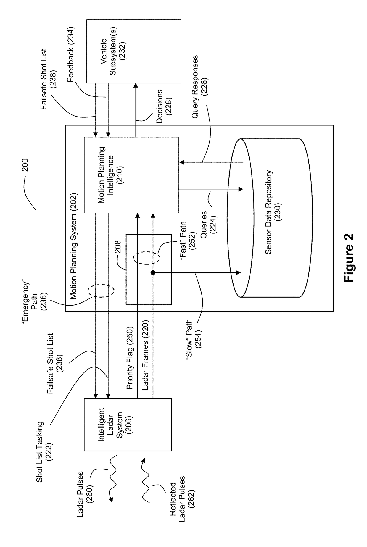
[0031]FIG. 2 discloses an example system 200 for vehicle autonomy with respect to motion planning. In this example, the motion planning system 202 interacts with a sensor such as an intelligent ladar system 206 in a manner where the intelligent ladar system 206 is able to provide fast path notifications regarding detected threats. Unlike the conventional master-slave hierarchical relationship between a motion planning system and sensor, the example embodiment of FIG. 2 employs a collaborative model of decision-making as between an intelligent ladar system 206 and the motion planning system 202, whereby some of the intelligence regarding object and anomaly detection is positioned in the intelligent ladar system 206. Also, it should be understood that the system 200 may include sensors other than intelligent ladar system 206 that provide information to the motion planning system 202 (e.g., one or more cameras, one or more radars, one or more acoustic sensors, one or more vehicle telem...


PUM


Abstract

Systems and methods are disclosed for vehicle motion planning where a sensor, such as a ladar system, is used to detect threatening or anomalous conditions within the sensor's field of view so that priority warning data about such conditions can be inserted at low latency into the motion planning loop of a motion planning computer system for the vehicle. The ladar system can perform compressive sensing to target the field of view with a plurality of ladar pulses.

Description

CROSS-REFERENCE AND PRIORITY CLAIM TO RELATED PATENT APPLICATIONS[0001]This patent application claims priority to U.S. provisional patent application 62 / 693,078, filed Jul. 2, 2018, and entitled “Intelligent Ladar System with Low Latency Motion Planning Updates”, the entire disclosure of which is incorporated herein by reference.[0002]This patent application also claims priority to U.S. provisional patent application 62 / 558,937, filed Sep. 15, 2017, and entitled “Intelligent Ladar System with Low Latency Motion Planning Updates”, the entire disclosure of which is incorporated herein by reference.[0003]This patent application is also related to (1) U.S. patent application Ser. No. ______, filed this same day, and entitled “Ladar Receiver with Co-Bore Sited Camera” (said application being identified by Thompson Coburn attorney docket number 56976-178394), (2) U.S. patent application Ser. No. ______, filed this same day, and entitled “Low Latency Intra-Frame Motion Estimation Based on ...

Claims


Application Information

Patent Timeline
IPC IPC(8): G01S17/93G01S17/02G01S7/481G01S17/42G01S17/89G01S7/4861G01S17/10G01S17/86G01S17/931
CPCG01S17/936G01S17/023G01S7/4817G01S17/42G01S17/89G01S7/484G01S17/10G01S17/86G01S17/931G01S7/4811G02B19/0028G02B19/0085G02B26/108G01S7/4814G01S7/4861
Inventor DUSSAN, LUIS CARLOSSTEINHARDT, ALLANBENSCOTER, JOEL DAVIDGREENE, JORDAN SPENCER
Owner AEYE INC
Why Eureka
Try Eureka