Display driver, electro-optical device, and electronic apparatus

a technology of electrooptical devices and electronic devices, applied in the direction of instruments, static indicating devices, etc., can solve the problem that the pixel cannot be driven at high speed, and achieve the effect of preventing an error in the gradation voltag

Active Publication Date: 2019-03-21
SEIKO EPSON CORP
View PDF3 Cites 10 Cited by
  • Summary
  • Abstract
  • Description
  • Claims
  • Application Information

AI Technical Summary

Benefits of technology

[0007]According to some aspects of the disclosure, a display driver, an electro-optical device, an electronic apparatus, and the like capable of speeding up a voltage change of an input node of an amplifier circuit that outputs data voltage are provided.
[0011]In this way, there are various advantages in contrast to advantages in a case where a noninverting amplifier circuit, an amplifier circuit using a capacitor as a feedback circuit, and the like is adopted. For example, an operating point of a differential pair of the operational amplifier is limited to the vicinity of a reference voltage, and thus the operational amplifier can be made to be highly sensitive (or highly gained). Alternatively, initialization is not needed unlike an inverting amplifier circuit using a capacitor as a feedback circuit.
[0013]In this way, the first to n-th buffers output the first to n-th voltages to the second ends of the first to n-th capacitors by the input data based on the display data, and thus the auxiliary electrical charge can be supplied from the first ends of the first to n-th capacitors to the input node of the amplifier circuit. A voltage change by redistributing an electrical charge can be achieved at a speed higher than a speed at which the voltage of the input node of the amplifier circuit changes. Thus, the voltage of the input node of the amplifier circuit can change at a high speed in the auxiliary period.
[0017]In this way, in the auxiliary period, the first current supply circuit passes a first auxiliary current from the node of the high electric potential side-power supply voltage to the input node of the amplifier circuit, or the second current supply circuit passes a second auxiliary current from the input node of the amplifier circuit to the node of the low electric potential side-power supply voltage. Thus, a capacity of the input node of the amplifier circuit can be charged. A voltage change by supplying a current can be achieved at a speed higher than a speed at which the D / A converter circuit changes the voltage of the input node of the amplifier circuit. Thus, the voltage of the input node of the amplifier circuit can change at a high speed in the auxiliary period.
[0021]In this way, the control circuit turns off the switches of the switch group in the auxiliary period, and thus the output of the D / A converter circuit can be set in the high impedance state. This can prevent the auxiliary current or the auxiliary electrical charge from flowing to the ladder resistance circuit through the D / A converter circuit in the auxiliary period. In other words, it is possible to prevent an error in a gradation voltage at the end of the auxiliary period from occurring.

Problems solved by technology

However, even when a speed of an output side of the amplifier circuit is increased, whereas a speed of an input side is not increased accordingly, a pixel may not be driven at high speed.

Method used


Image

  • Display driver, electro-optical device, and electronic apparatus
  • Display driver, electro-optical device, and electronic apparatus
  • Display driver, electro-optical device, and electronic apparatus

Examples


Embodiment Construction

[0041]Hereinafter, some exemplary embodiments of the disclosure will be described in detail. Note that some exemplary embodiments described below do not unreasonably limit contents of the disclosure described in claims, and all configurations described in some exemplary embodiments do not have to be indispensable matters of the disclosure.

1. Display Driver

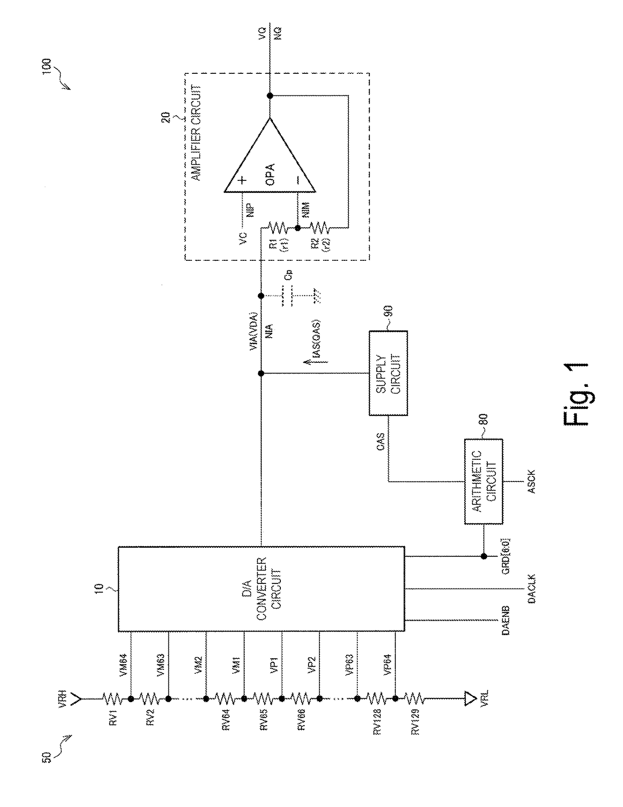
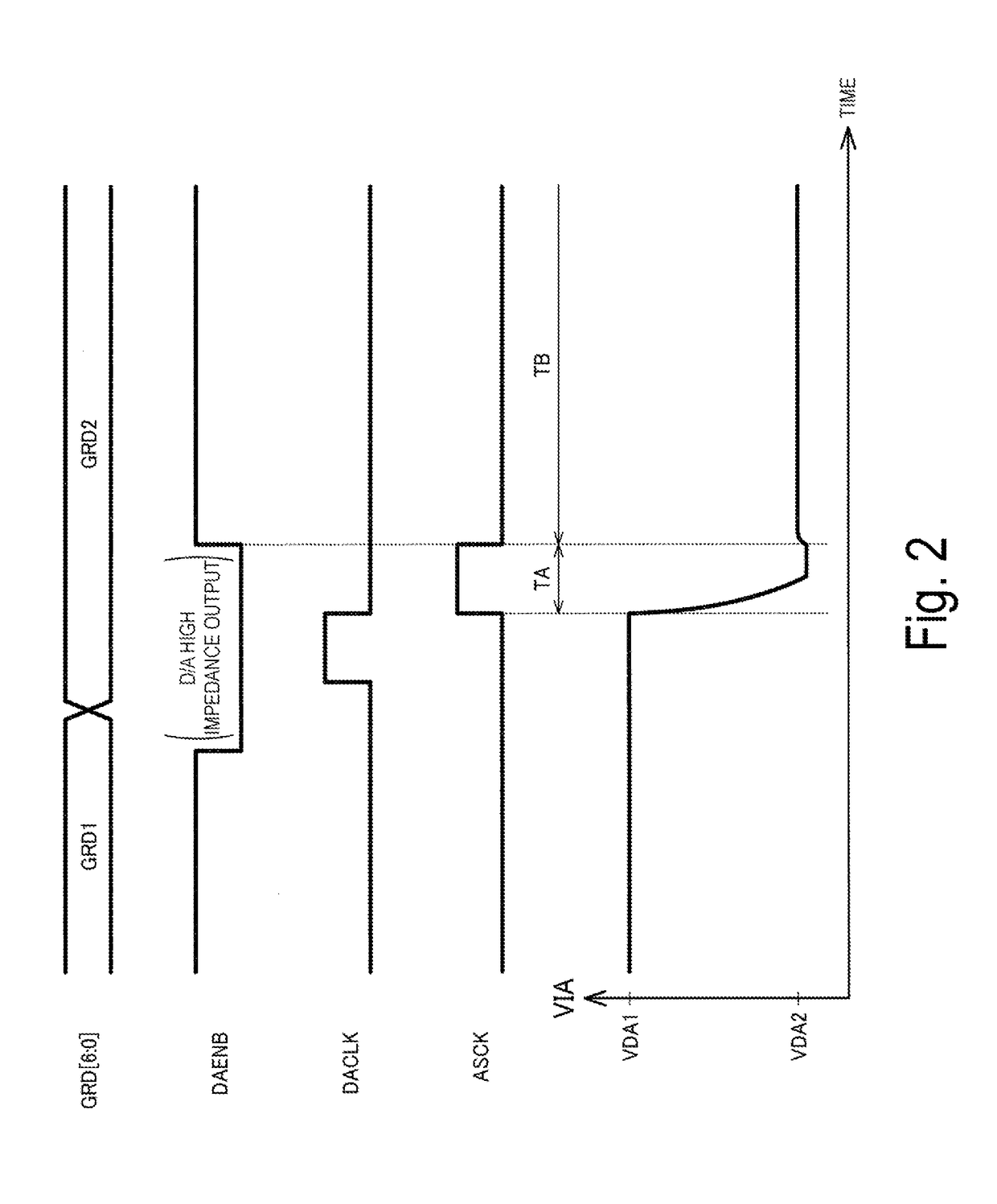
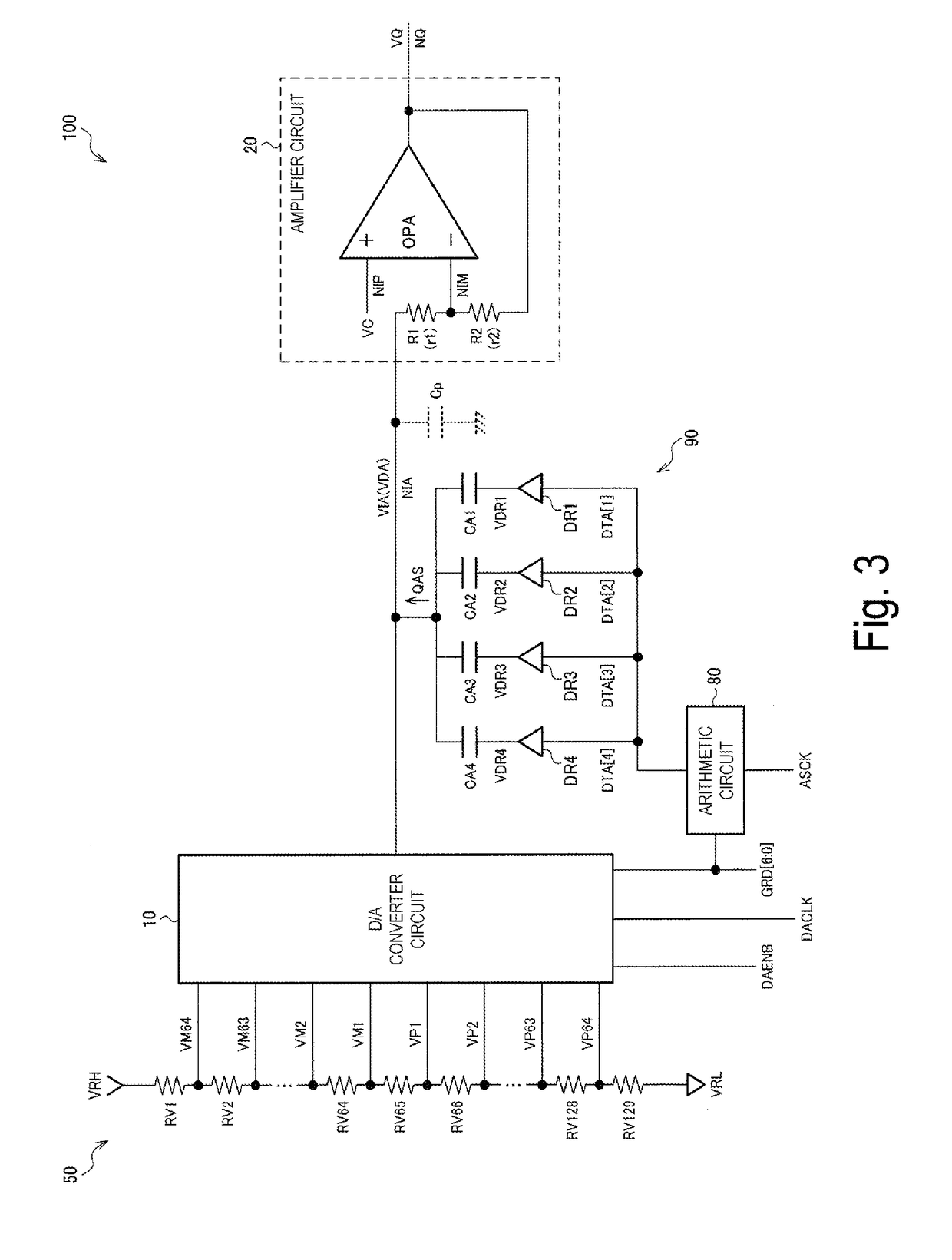
[0042]FIG. 1 is an example of a configuration of a display driver 100 in one exemplary embodiment. The display driver 100 includes a D / A converter circuit 10, an amplifier circuit 20, and a supply circuit 90. The display driver 100 can also include a ladder resistance circuit 50 (gradation voltage generating circuit) and an arithmetic circuit 80 (second arithmetic circuit, control circuit). The display driver 100 is configured by, for example, an integrated circuit (IC) device. Note that the disclosure is not limited to the configuration of FIG. 1, and various modifications can be achieved by, for example, omitting a part of the co...


PUM


Abstract

A display driver includes a D / A converter circuit configured to convert display data into a gradation voltage, an amplifier circuit including an input node to which the gradation voltage is input and configured to output data voltage, and a supply circuit configured to supply an auxiliary current or an auxiliary electrical charge to the input node of the amplifier circuit. In an auxiliary period, an output of the D / A converter circuit is in a high impedance state, and the supply circuit supplies the auxiliary current or the auxiliary electrical charge to the input node of the amplifier circuit. In a non-auxiliary period after the auxiliary period, the D / A converter circuit outputs the gradation voltage to the input node of the amplifier circuit.

Description

[0001]The present application is based on and claims priority from JP Application Serial Number 2017-181068, filed Sep. 21, 2017, the disclosure of which is hereby incorporated by reference herein in its entirety.BACKGROUND1. Technical Field[0002]The disclosure relates to a display driver, an electro-optical device, and an electronic apparatus.2. Related Art[0003]A display driver that drives an electro-optical panel includes a ladder resistance circuit that generates a plurality of voltages, a D / A (digital-to-analog) converter circuit that selects a gradation voltage corresponding to display data from the plurality of voltages, and an amplifier circuit that amplifies or buffers (performs impedance conversion on) the gradation voltage. A related technology of such a display driver is disclosed in, for example, JP-A-2005-292856, JP-A-2001-67047, and JP-A-10-260664.[0004]In JP-A-2005-292856, an amplifier circuit is formed of a forward amplifier circuit. In other words, a gradation volt...

Claims


Application Information

Patent Timeline
Patent Type & Authority Applications(United States)
IPC IPC(8): G09G3/36
CPCG09G3/3688G09G3/3696G09G2320/0252G09G2310/027G09G3/20
Inventor MORITA, AKIRA
Owner SEIKO EPSON CORP
Why Eureka
Try Eureka