Half bridge resonant converters, circuits using them, and corresponding control methods

a resonant converter and half bridge technology, applied in the direction of electric variable regulation, process and machine control, instruments, etc., can solve the problems of additional power dissipation, hard switching, switching loss, etc., and achieve the effect of reducing or eliminating switching losses

Active Publication Date: 2019-03-21
SIGNIFY HLDG BV
View PDF0 Cites 9 Cited by
  • Summary
  • Abstract
  • Description
  • Claims
  • Application Information

AI Technical Summary

Benefits of technology

[0053]This converter makes use of separate circuits for generating the gate drive signals for the two power switches of the inverter, each with their own voltage domain. In this way, the circuits can use primarily low voltage components, with the number of high voltage components reduced to a minimum.
[0054]One circuit is referenced to ground and the oth

Problems solved by technology

If the output current is not large enough or even zero and further depending on the operation conditions (in terms of the half bridge, output, and resonant capacitor voltage), discharging of the parasitic output capacitance will be partly or even completely achieved by the power switch which results in hard switching.
This results in switching losses which depend on the switching frequency, the parasitic output capacitance of the switch and the voltage across the parasitic capacitance at switch-on.
Ho

Method used


Image

  • Half bridge resonant converters, circuits using them, and corresponding control methods
  • Half bridge resonant converters, circuits using them, and corresponding control methods
  • Half bridge resonant converters, circuits using them, and corresponding control methods

Examples


Embodiment Construction

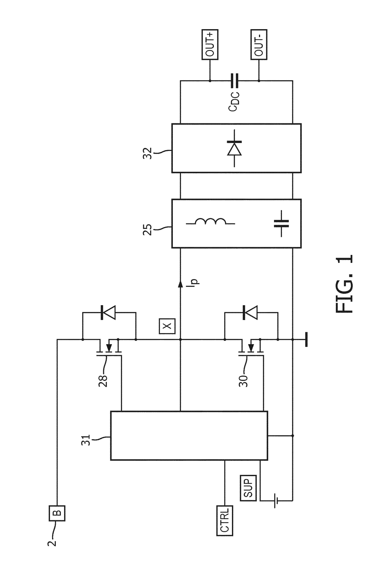
[0119]The invention provides a half bridge resonant converter comprising a half bridge inverter having a high side switch and a low side switch with an output defined from a switch node between the high side switch and the low side switch. The output connects to a resonant circuit. There are separate control circuits for generating the gate drive signals for controlling the switching of the high side switch and low side switch, in dependence on an electrical feedback parameter, each with different reference voltage supplies.

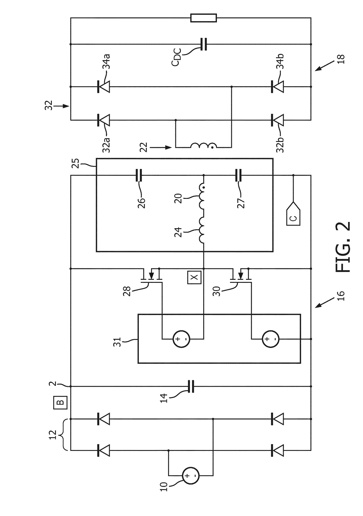
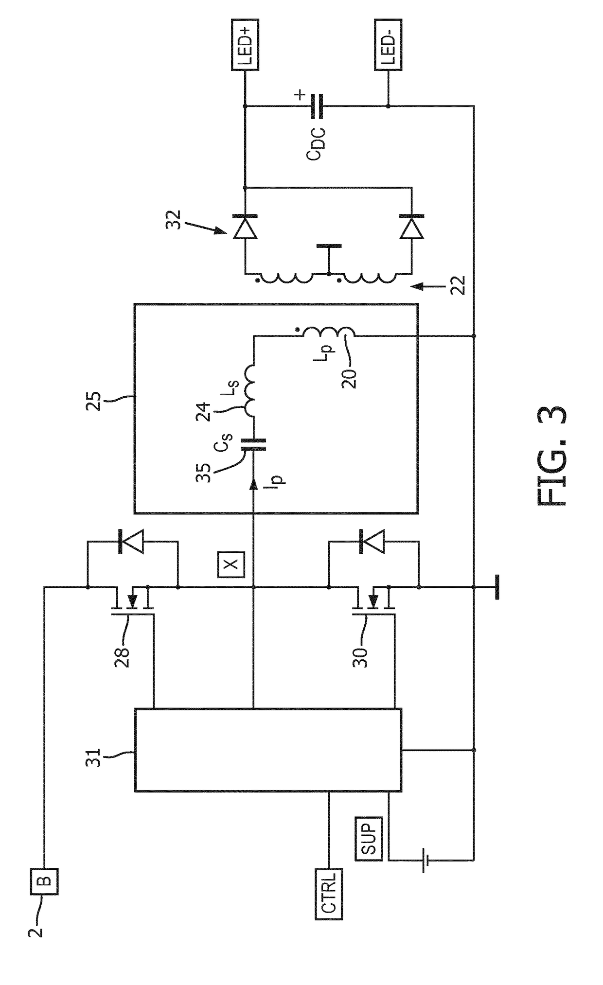
[0120]FIG. 6 shows converter using a half bridge topology with an LLC resonant tank circuit 25 and a full wave rectifier 32 controlled by two local control circuits.

[0121]The converter is supplied by a pair of DC voltage lines comprising a DC high voltage line 60 (node B) and a low voltage line 62, e.g. ground. As in the examples above, the half bridge inverter comprises a high side switch 28 and a low side switch 30 in series between the high voltage line 60 and...


PUM


Abstract

A half bridge resonant converter comprises a half bridge inverter having a high side switch and a low side switch with an output defined from a node between the high side switch and the low side switch. The output connects to a resonant circuit. There are separate control circuits for generating the gate drive signals for controlling the switching of the high side switch and low side switch, in dependence on an electrical feedback parameter, each with different reference voltage supplies.

Description

FIELD OF THE INVENTION[0001]This invention relates to the use of half bridge resonant converters. By way of example, such resonant converters may be used to form part of a power converter to provide AC / DC conversion, to provide DC / DC conversion, to provide AC / DC conversion with power factor correction, or to provide DC / AC conversion, i.e. inversion.BACKGROUND OF THE INVENTION[0002]So-called resonant converters have a resonant circuit, which can be a series or parallel or series-parallel resonant circuit. When configuring converters, one aim is to keep losses low. For example, resonant converters which comprise an LLC series-parallel resonant circuit having two inductances and one capacitance are well-known. Such converters have the advantage that energy-efficient operation with relatively low switching losses is possible.[0003]Resonant LLC converters are well known for use within LED drivers. The converters can be configured or operated as a constant current source or a constant vol...

Claims


Application Information

Patent Timeline
IPC IPC(8): H02M3/337H02M7/5383H02M1/08H05B44/00
CPCH02M3/3378H02M7/53832H02M1/08H02M3/335H05B45/39Y02B20/30Y02B70/10H05B45/382H02M7/4815H02M3/33571H02M3/01H02M3/07H02M7/537
Inventor OP HET VELD, JOHANNES HUBERTUS GERARDUSJOHN, DAVID LLEWELLYNELFERICH, REINHOLDJANS, WILLIAM PETER MECHTILDIS MARIE
Owner SIGNIFY HLDG BV
Why Eureka
Try Eureka