
Detection device and method for improving layer-to-layer transition of steel wire ropes

a detection device and a technology for lifting steel wire ropes, applied in the direction of lifting equipment, apparatus for force/torque/work measurement, elevators, etc., can solve the problems of affecting the service life of steel wire ropes, unable to meet the function requirements of single-layer winding, and various mechanical damag

Inactive Publication Date: 2019-03-28
CHINA UNIV OF MINING & TECH
View PDF0 Cites 12 Cited by
  • Summary
  • Abstract
  • Description
  • Claims
  • Application Information

AI Technical Summary

Benefits of technology

The present invention provides a friction detection device and an experimental method for simulating and measuring the friction force on a steel wire rope when it is wound around a reel for multiple layers and about to form a further layer. The device can detect the layer-to-layer transition of the lifting steel wire rope and can measure the torque experienced by the steel wire rope. The device is easy to change the rope and has high efficiency. The technical effects of the invention include the ability to simulate and measure the friction force on steel wire rope when it is wound around a reel for multiple layers and about to form a further layer.

Problems solved by technology

During operation, a steel wire rope may bear various loads at the same time such as tensioning, bending, twisting, and compressing, and may also experience various mechanical damages.
In many cases, single-layer winding cannot adequately meet the function requirements.
During transitioning from the previous layer to the next layer, the steel wire rope undergoes complex forces and frictions, which greatly affect the service life of the steel wire rope.

Method used


Image

  • Detection device and method for improving layer-to-layer transition of steel wire ropes
  • Detection device and method for improving layer-to-layer transition of steel wire ropes
  • Detection device and method for improving layer-to-layer transition of steel wire ropes

Examples


Embodiment Construction

[0042]The following describes in detail the present invention with reference to specific embodiments.

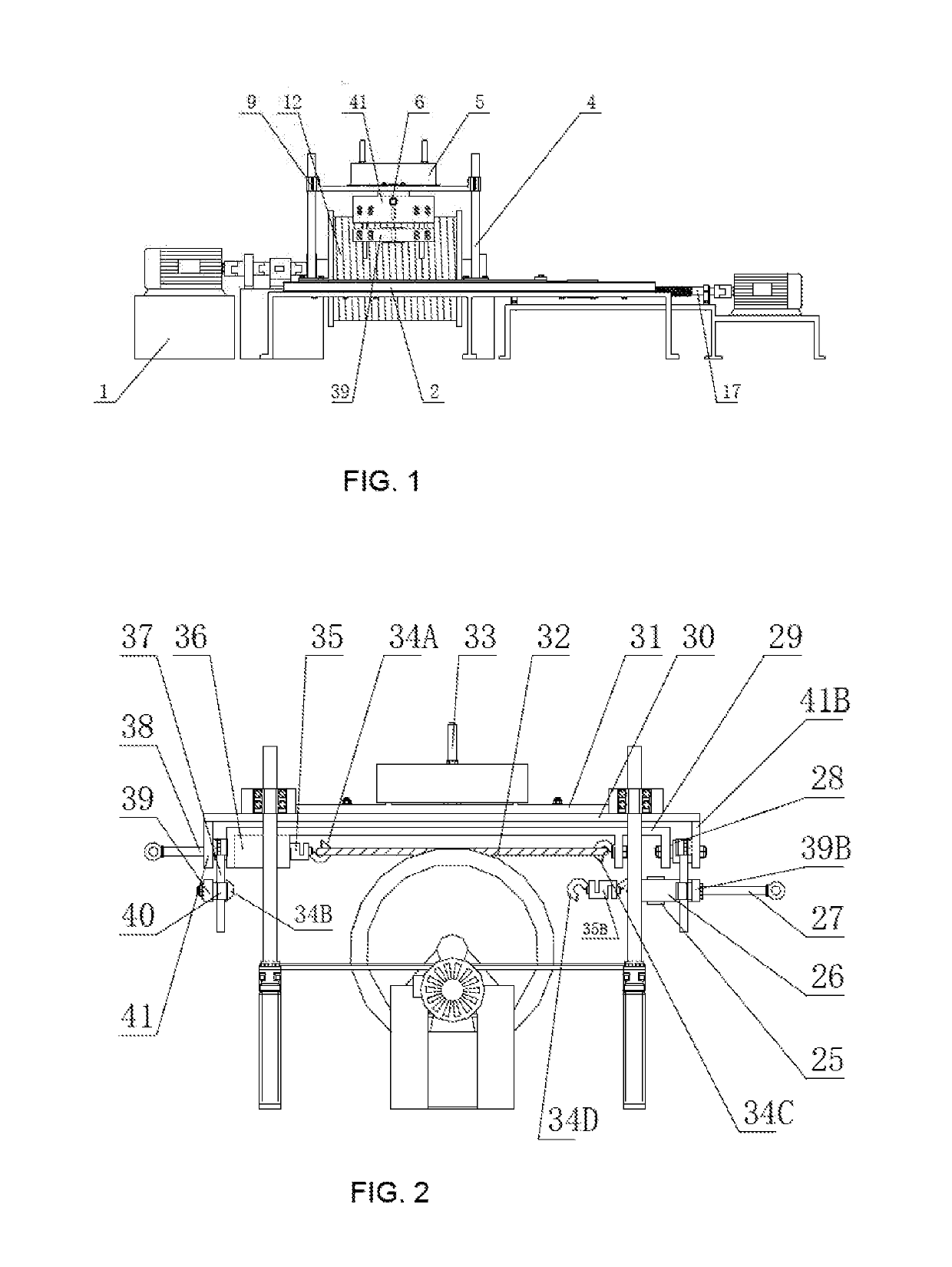
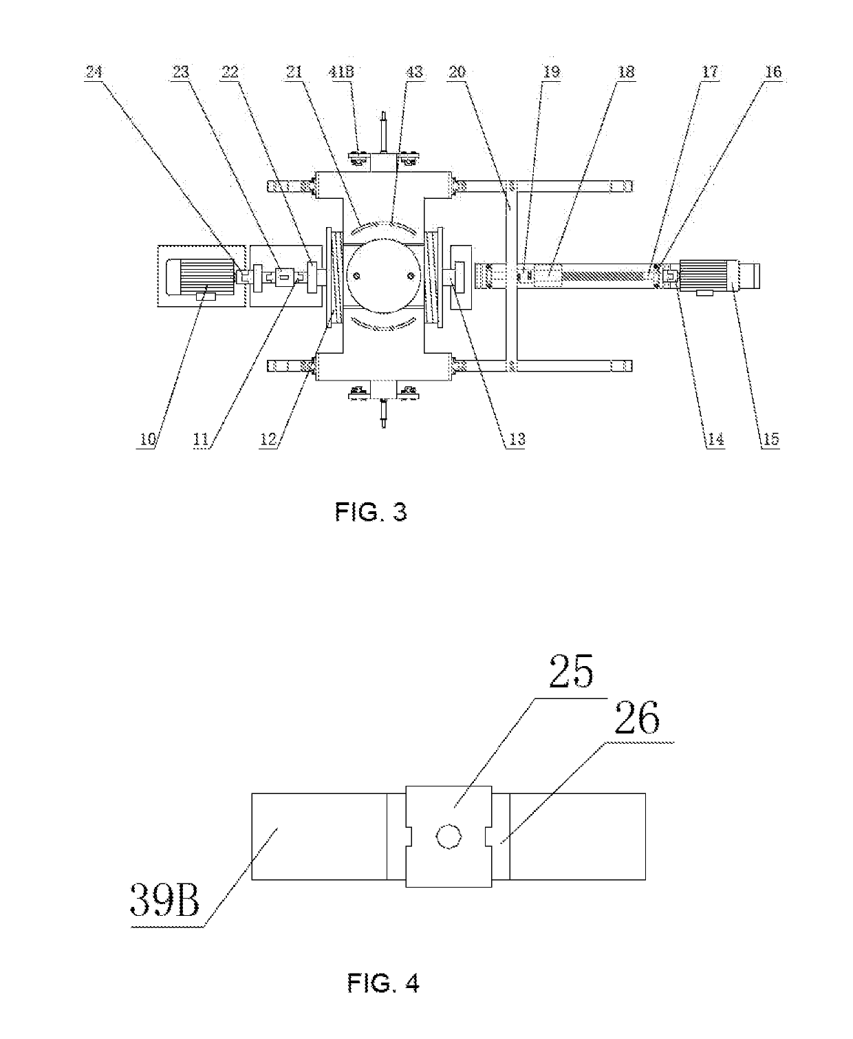
[0043]As shown in FIG. 1, a device for detecting layer-to-layer transition of a lifting steel wire rope includes a reel assembly, a steel wire rope tensioning assembly, a steel wire rope loading assembly, and a lead screw sliding assembly, where the reel assembly is used to wind a steel wire rope around a reel, and can drive the reel to rotate; the steel wire rope tensioning assembly is used to tension a steel wire rope; the steel wire rope loading assembly is used to provide vertical loading for the steel wire rope tensioning assembly, so that loading force is generated between the tensioned steel wire rope and the steel wire rope wound around the reel; the lead screw sliding assembly is used to drive the steel wire rope tensioning assembly to move on a guide rail 2, so that there is a relative displacement between the tensioned steel wire rope and the steel wire rope wound around t...


PUM


Abstract

Systems and methods for detecting a layer-to-layer transition of a lifting steel wire rope on a reel are described. The system includes a reel assembly for winding a steel wire rope on a reel and a tensioning assembly for tensioning a segment of said steel wire rope. The system further includes a loading assembly and a lead screw sliding assembly. The loading assembly provides a vertical loading to the tensioning assembly so as to generate a loading force between the tensioned steel wire rope and the steel wire rope wound around the reel. The lead screw sliding assembly drives the tensioning assembly so as to move on a horizontal guide rail to generate a relative displacement between the tensioned steel wire rope and the steel wire rope wound around the reel. The tensioning assembly is connected to the loading assembly via a first threaded rod and a static torque sensor.

Description

RELATED APPLICATIONS[0001]This application is the U.S. National phase of International Application No. PCT / CN2017 / 075380 filed on Mar. 2, 2017, and claims priority to Chinese Patent Application No. 201610124152.1, filed on Mar. 4, 2016, which are hereby expressly incorporated by reference in their entirety for all purposes.TECHNICAL FIELD[0002]The present invention relates to a device and a method for detecting layer-to-layer transition of a lifting steel wire rope, applicable to simulating friction and vibration behaviors and states of a steel wire rope when the steel wire rope is wound around a reel and is about to form a further layer, so as to provide a detection means suitable for the design and optimization of multi-layer winding of a lifting and winding device.BACKGROUND OF THE DISCLOSURE[0003]Lifting and winding devices are usually used in engineering fields, such as for example, in various hoisting machines and mine hoists. During operation, a steel wire rope may bear vario...

Claims


Application Information

Patent Timeline
IPC IPC(8): G01N19/02G01L5/06
CPCG01N19/02G01L5/06B66D1/00B66D1/54B66D1/28B66D1/38B66D1/46G01L5/042B66B5/00
Inventor PENG, YUXINGZHU, ZHENCAIXU, WENXUESHI, ZHIYUANGONG, XIANSHENGCHANG, XIANGDONGWANG, DAGANGCAO, GUOHUALIU, SONGYONG
Owner CHINA UNIV OF MINING & TECH
Learn More