Light-emitting diode and light-emitting device including the same

Active Publication Date: 2019-03-28
LG DISPLAY CO LTD
View PDF0 Cites 5 Cited by
  • Summary
  • Abstract
  • Description
  • Claims
  • Application Information

AI Technical Summary

Benefits of technology

[0014]An aspect of the present disclosure is to provide a light-emitting diode in which electric charges may be injected into an emitting material layer in a balanced manner, and a light-emitting de

Problems solved by technology
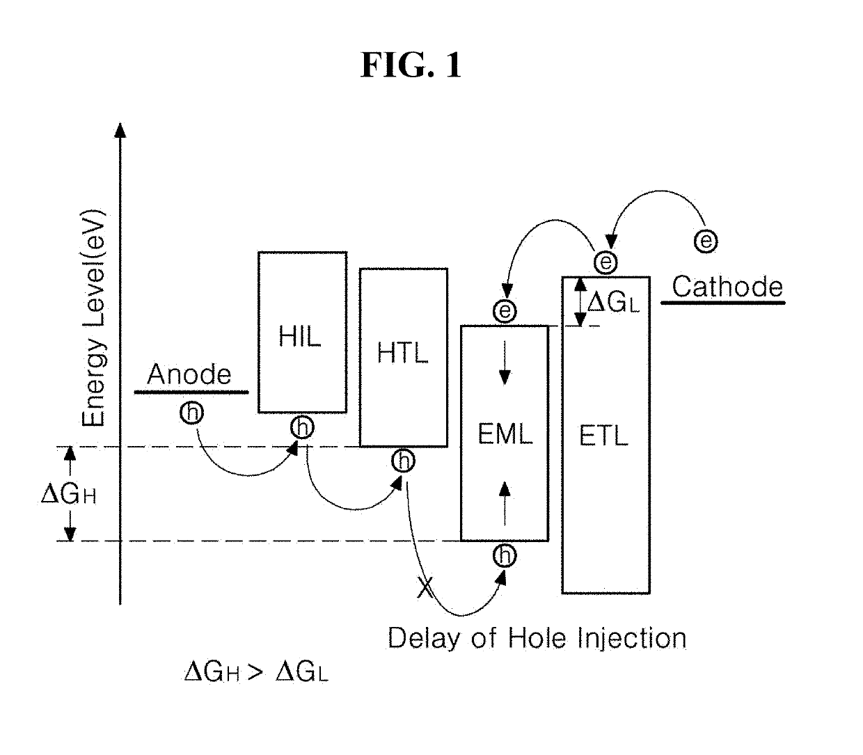
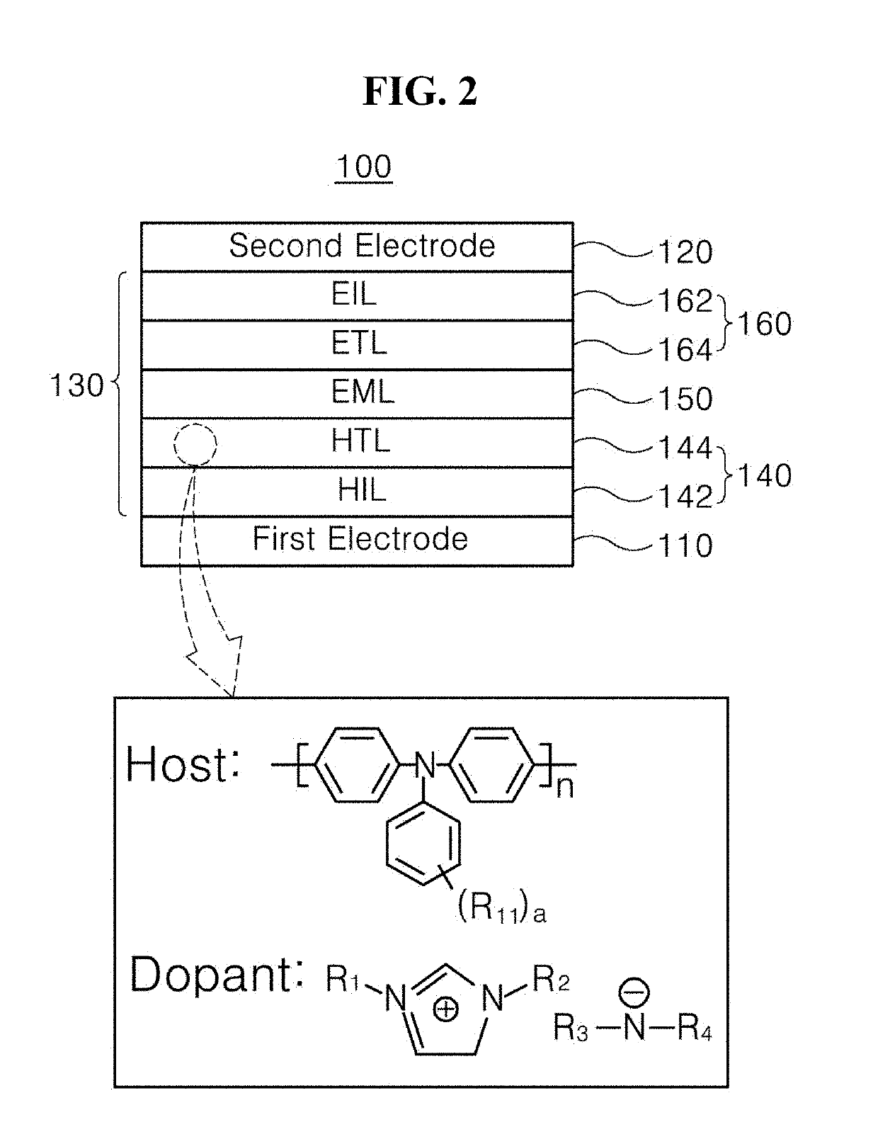
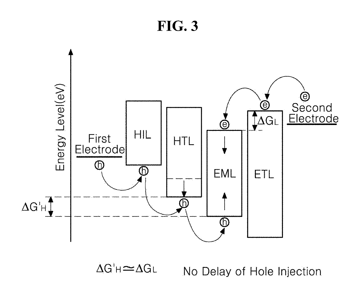
Therefore, as the transport/injection of holes into the emitting material layer EML is delayed when compared to the transport/injection of electrons into the emitting material layer EML, electric charges may not be injected into the emitting material layer EML in a balanced manner.
Such a problem i

Method used


Image

  • Light-emitting diode and light-emitting device including the same
  • Light-emitting diode and light-emitting device including the same
  • Light-emitting diode and light-emitting device including the same

Examples


Example

Synthesis Example 1: Synthesis of Compound HT01

[0138](1) Synthesis of A3

[0139]3.0 g (36.5 mmol) of A1 and 7.76 g (39.9 mmol) of A2 were dissolved in 50 mL of acetonitrile in a 250-mL round-bottom flask and then were heated and stirred for 72 hours. After the reaction was completed, the acetonitrile was removed. Then, extraction was performed using dichloromethane and water and then vacuum distillation was performed. After silica gel column chromatography was performed, a solvent was subjected to vacuum distillation to obtain 7.54 g of Compound A3 (yield: 75%).

[0140](2) Synthesis of HT01

[0141]3.0 g (10.8 mmol) of A3 and 4.69 g (16.2 mmol) of LiN(CF3SO2)2 were dissolved in 120 mL of ethanol in a 250-mL round-bottom flask and then were stirred at room temperature for 24 hours. After the reaction was completed, extraction was performed using dichloromethane and water and then vacuum distillation was performed. After silica gel column chromatography was performed, a solvent was subjected...

Example

Synthesis Example 2: Synthesis of Compound HT02

[0142]

[0143]3.0 g (10.8 mmol) of A3 and 6.27 g (16.2 mmol) of LiN(C2F5SO2)2 were dissolved in 120 mL of ethanol in a 250-mL round-bottom flask and then were stirred at room temperature for 24 hours. After the reaction was completed, extraction was performed using dichloromethane and water and then vacuum distillation was performed. After silica gel column chromatography was performed, a solvent was subjected to vacuum distillation to obtain 5.39 g of Compound HT02 (yield: 86%).

Example

Synthesis Example 3: Synthesis of Compound HT03

[0144]

[0145]3.0 g (10.8 mmol) of A3 and 1.20 g (16.2 mmol) of LiN(CN)2 were dissolved in 120 mL of ethanol in a 250-mL round-bottom flask and then were stirred at room temperature for 24 hours. After the reaction was completed, extraction was performed using dichloromethane and water and then vacuum distillation was performed. After silica gel column chromatography was performed, a solvent was subjected to vacuum distillation to obtain 2.11 g of Compound HT03 (yield: 74%).


PUM

PropertyMeasurementUnit
Fractionaaaaaaaaaa
Fractionaaaaaaaaaa
Fractionaaaaaaaaaa

Abstract

The present disclosure relates to a light-emitting diode (LED) in which an organic compound including an imidazolium-based cationic moiety and an amine-based anionic moiety substituted with a strong electron-withdrawing group such as a sulfonyl group or a cyano group is applied to a hole transfer layer, and a light-emitting device. By applying the organic compound according to the present disclosure to the hole transfer layer, an energy barrier between the hole transport layer and an emitting material layer is removed, and an LED having improved hole transport properties can be designed. Therefore, it is possible to realize and manufacture an LED and a light-emitting device, driven at a low voltage and having improved luminous efficiency.

Description

CROSS-REFERENCE TO RELATED APPLICATIONS[0001]This application claims the benefit under 35 U.S.C. § 119(a) of Korean Patent Application No. 10-2017-0126435 filed in Korea on Sep. 28, 2017, which is incorporated herein by reference in its entirety.BACKGROUNDTechnical Field[0002]The present disclosure relates to a light-emitting diode, and more specifically, to a light-emitting diode having improved luminous efficiency, and a light-emitting device including the same.Discussion of the Related Art[0003]With the advancement of electronic engineering and information technology, technology of the display field for processing and displaying a massive amount of information has also been rapidly developed. Accordingly, various flat panel display devices replacing the cathode ray tube (CRT) have been developed. Among flat panel display devices, since an organic light-emitting diode (OLED) display device and a quantum dot light-emitting diode (QLED) display device may be formed in a thin structu...

Claims


Application Information

Patent Timeline
IPC IPC(8): H01L51/00H01L51/50H01L51/52H01L27/32
CPCH01L51/0067H01L51/0059H01L51/502H01L51/5004H01L51/5092H01L51/5206H01L51/5221H01L27/3244H01L51/5072H01L51/5056H01L51/5096H10K59/12H10K85/631H10K50/155H10K85/115H10K85/111H10K85/151H10K85/654H10K50/115C09K11/06H10K85/113H10K85/633H10K50/15H10K50/11H10K50/81H10K50/82H10K50/171H10K50/16H10K50/18H10K2101/40
Inventor LEE, NA-YEONLEE, SEUNG-JAEBIN, JONG-KWAN
Owner LG DISPLAY CO LTD
Why Eureka
Try Eureka