Trigger devices for exothermic welds

a technology of exothermic welding and trigger device, which is applied in the direction of alumino-thermic welding apparatus, soldering apparatus, light and heating apparatus, etc., can solve problems such as potential danger

Active Publication Date: 2019-04-04
HUBBELL INC
View PDF0 Cites 5 Cited by
  • Summary
  • Abstract
  • Description
  • Claims
  • Application Information

AI Technical Summary

Benefits of technology

[0006]In an exemplary embodiment of the trigger device, the trigger device is a flint trigger device where a flint is used to generate a spark to ignite a starting powder on an exothermic mold. In an exemplary embodiment, the flint trigger device includes a housing having a spark opening on a rear wall of the housing, a mold mounting assembly, a motor assembly, a flint assembly and a controller. The mold mounting assembly is secured to an exterior of the rear wall of the housing. The motor assembly is secured to the rear wall of the housing and in the interior of the housing. The motor assembly has a flint wheel attached to a shaft of a motor such that the flint wheel is located adjacent the spark opening in the housing. The flint assembly is secured within the housing and is positioned so that a flint of the flint assembly is in contact with the flint wheel of the motor assembly so that rotation of the motor causes the flint and flint wheel to generate one or more sparks. The controller, which may be a printed circuit board assembly, is positioned within the housing and is configured to selectively activate the motor to cause the flint wheel to rotate against the flint to create the one or more sparks which are to be ejected from the spark opening in the housing onto a starting powder when in use. In the above described flint trigger device, the device is an electro-mechanical device where a motor is used to rotate a flint wheel to generate the one or more sparks. In another exemplary embodiment, the flint trigger device may be a mechanical device that uses mechanical mechanisms, such as stored energy from a mainspring, to rotate a flint or drive wheel to generate the one or more sparks.
[0007]In an exemplary embodiment of the kit, the kit includes an exothermic mold and a flint trigger device. The exothermic mold may be a horizontal exothermic mold or a vertical exothermic mold. The flint trigger device includes a housing having a spark opening on a rear wall of the housing, a mold mounting assembly, a motor assembly, a flint assembly and a controller. The mold mounting assembly is secured to an exterior of the rear wall of the housing. The motor assembly is secured to the rear wall of the housing and in the interior of the housing. The motor assembly has a flint wheel attached to a shaft of a motor such that the flint wheel is located adjacent the spark opening in the housing. The flint assembly is secured within the housing and is positioned so that a flint of the flint assembly is in contact with the flint wheel of the motor assembly so that rotation of the motor causes the flint and flint wheel to generate one or more sparks. The controller, which may be a printed circuit board assembly, is positioned within the housing and is configured to selectively activate the motor to cause the flint wheel to rotate against the flint to create the one or more sparks which are to be ejected from the spark opening in the housing onto a starting powder when in use. In the above described flint trigger device, the device is an electro-mechanical device where a motor is used to rotate a flint wheel to generate the one or more sparks. In another exemplary embodiment, the flint trigger device may be a mechanical device that uses mechanical mechanisms, such as stored energy from a mainspring, to rotate a flint or drive wheel to generate the one or more sparks.
[0008]In an exemplary embodiment of the method for igniting an exothermic reaction within an exothermic mold, the method includes inserting a disc of welding material into a crucible within the exothermic mold, pouring an exothermic reaction powder into the crucible, mounting a flint trigger device to the mold, pouring a starting powder into an opening in a cover of the mold such that a mound of starting powder rests on the cover of the mound, and activating the flint trigger device to eject the one or more sparks from the spark opening in the housing such that the one or more sparks impact the starting powder causing the starting powder to ignite. In this exemplary embodiment, the flint trigger device includes a housing having a spark opening on a rear wall of the housing, a mold mounting assembly, a motor assembly, a flint assembly and a controller. The mold mounting assembly is secured to an exterior of the rear wall of the housing. The motor assembly is secured to the rear wall of the housing and in the interior of the housing. The motor assembly has a flint wheel attached to a shaft of a motor such that the flint wheel is located adjacent the spark opening in the housing. The flint assembly is secured within the housing and is positioned so that a flint of the flint assembly is in contact with the flint wheel of the motor assembly so that rotation of the motor causes the flint and flint wheel to generate one or more sparks. The controller, which may be a printed circuit board assembly, is positioned within the housing and is configured to selectively activate the motor to cause the flint wheel to rotate against the flint to create the one or more sparks which are to be ejected from the spark opening in the housing onto a starting powder when in use. In the above described flint trigger device, the device is an electro-mechanical device where a motor is used to rotate a flint wheel to generate the one or more sparks. In another exemplary embodiment, the flint trigger device may be a mechanical device that uses mechanical mechanisms, such as stored energy from a mainspring, to rotate a flint or drive wheel to generate the one or more sparks.

Problems solved by technology

Because the exothermic reaction occurs so quickly, this method forces the technician igniting the ignition powder to be in close proximity to the sparks, flames and hot gasses discharged from the mold may create a potential hazardous situation.

Method used


Image

  • Trigger devices for exothermic welds
  • Trigger devices for exothermic welds
  • Trigger devices for exothermic welds

Examples


Embodiment Construction

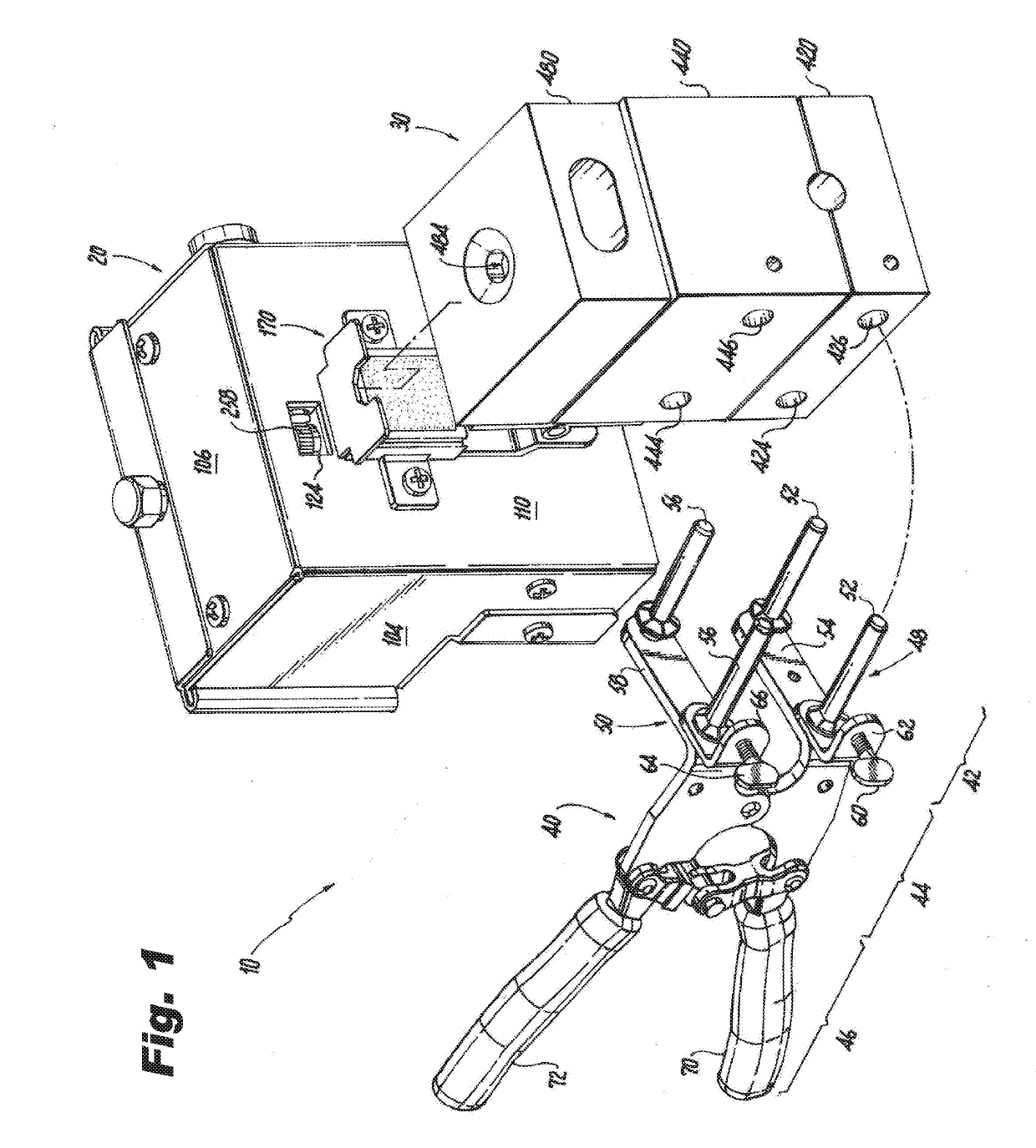
[0043]The present disclosure provides embodiments of trigger devices for igniting exothermic reactions. The present disclosure also provides embodiments of kits for making exothermic welds that include an exothermic reaction mold and a trigger device according to the present disclosure, and may also include an exothermic weld mold clamp. The trigger devices may be flint type trigger devices, electronic type trigger devices or electric type trigger devices. For ease of description, the trigger devices of the present disclosure may also be referred to as the “device” in the singular and the “devices” in the plural. The exothermic reaction molds may be referred to as the “mold” in the singular and the “molds” in the plural. The exothermic weld mold clamp may be referred to as the “handle clamp” in the singular and the “handle clamps” in the plural.

[0044]Referring to FIG. 1, an exemplary embodiment of a kit for making exothermic welds is shown. In this exemplary embodiment, the kit 10 i...


PUM

PropertyMeasurementUnit
angleaaaaaaaaaa
angleaaaaaaaaaa
angleaaaaaaaaaa

Abstract

Trigger devices for igniting an exothermic reaction is provided. The trigger devices may be flint type trigger devices and electronic type trigger devices. The flint type trigger device has a housing with a spark opening on a rear wall of the housing. A mold mounting assembly is secured to an exterior of the rear wall of the housing. A motor assembly is secured to the inside of the rear wall of the housing. The motor assembly has a flint wheel attached to a shaft of a motor, where the flint wheel is located adjacent the spark opening. A flint assembly is positioned within the housing such that a flint of the flint assembly is in contact with the flint wheel. A controller positioned within the housing is configured to selectively activate the motor to cause the flint wheel to rotate against the flint to create one or more sparks that are ejected from the spark opening.

Description

CROSS REFERENCE TO RELATED APPLICATIONS[0001]The present disclosure is based on and claims benefit from co-pending U.S. Provisional Patent Application Ser. No. 62 / 567,294 filed on Oct. 3, 2017 entitled “Flint Trigger Devices for Exothermic Welds” the entire contents of which are incorporated herein by reference.BACKGROUNDField[0002]The present disclosure relates to trigger devices used to ignite a starting powder on an exothermic mold or a weld metal powder within the exothermic mold, and to exothermic welding kits that include a trigger device according to the present disclosure.Description of the Related Art[0003]Exothermic reaction welding is often used for providing a permanent joint between metal parts including ground rods, electrical conductors, wire cables, piping, etc. Exothermic reaction welding involves the use of a mold, a disc, an exothermic weld metal powder and a mechanism for igniting the weld metal powder. When the weld metal powder is ignited, an exothermic reactio...

Claims


Application Information

Patent Timeline
Patent Type & Authority Applications(United States)
IPC IPC(8): F23Q1/02B23K23/00
CPCF23Q1/02B23K23/00B23K1/0006
Inventor HOAGLAND, TIMOTHY CHARLESCEASS, RICHARD WALLACEABEDRABOH, MAMOON TAWFIQ
Owner HUBBELL INC
Why Eureka
Try Eureka