
Apparatus and Methods for Vehicle Battery Charging or Voltage Monitoring

a technology for vehicle batteries and charging devices, applied in the direction of coupling device connections, instruments, transportation and packaging, etc., can solve the problems of battery depletion, parasitic load, and particularly acute problem of battery depletion

Inactive Publication Date: 2019-04-11
SHENZHEN PRIME LOGIC TECH CO LTD
View PDF6 Cites 9 Cited by
  • Summary
  • Abstract
  • Description
  • Claims
  • Application Information

AI Technical Summary

Benefits of technology

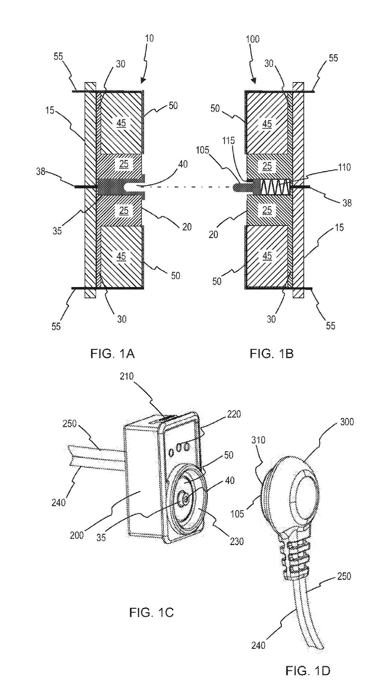
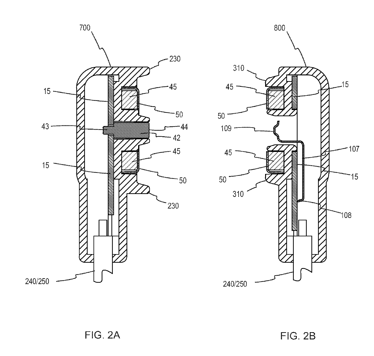
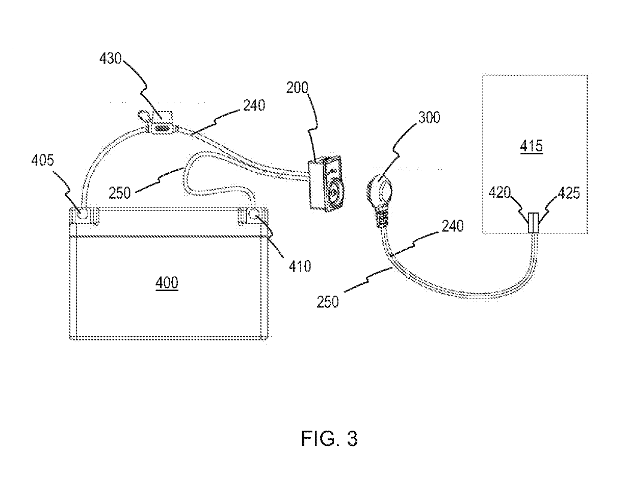
The present invention provides an electrical connector for charging or monitoring a vehicle's rechargeable battery. The connector has a first conducting portion that can conduct enough electrical energy to charge the battery, and a magnetically attractive portion that can be attracted to a complementary magnetically attractive portion on another connector. The connectors can be easily connected and disconnected, and the magnetically attractive portions can be manually broken after use. The connector system can be used to recharge or monitor the battery of a vehicle with a rechargeable battery.

Problems solved by technology

A problem arises in that parasitic load on the vehicle's circuit can deplete the battery to the point that it is not fully charged during operation of the combustion engine.
The parasitic load may be caused by the operation of electronic componentry such as entertainment systems, navigation systems, safety systems (such as collision avoidance and tyre pressure monitoring systems).
For vehicles having fuel saving stop / start ignitions systems the problem of battery depletion is particularly acute.
Accordingly, it is not uncommon for the vehicle battery to be depleted to the point that it is incapable of cranking the combustion engine.
A further problem is that the depletion of lead / acid batteries has a negative effect on the battery per se.
This leads to the development of large crystals that reduce the ability of the battery to store and delivery electrical power when required.
This process is known as “sulfation” and is the main cause of early battery failure.
The vehicle is driven around by the user, and in the course of use the battery discharges an eventually becomes depleted.
This requires access to the battery (often disposed in the engine bay, or in the trunk area), and is generally inconvenient.
Many prior art connectors have one or more problems.
One problem is that users forget to disconnect the power supply before driving the vehicle.
It is often the case that the vehicle battery requires charging over any extended period (such as overnight) and by the time the user returns to use the vehicle, any memory of having connected the vehicle is diminished or lost.
Even in such decoupling, some force is applied to the connectors and cable which, over time, may be incrementally damaged to the point of eventual failure.
Even before complete failure, the connection may become unreliable over time, and in some instances may even present a fire hazard due to arcing.
Where the connectors are robustly coupled (for example, where a latch arrangement is used to secure the connectors together) significant damage to the vehicle or power supply will occur if the user drives away without first decoupling the connectors.
A connector may be ripped away from the cable to which it is fitted, this causing a significant electric shock hazard given the exposure of wires where mains voltages are involved.
Such connectors are, of course, prone to inadvertent disconnection by the connectors being uncoupled by even a gentle knock, or a disturbance by the wind.
Furthermore, while a loose connection is relatively easy to uncouple by a user, such connections can lead to a drop in voltage over the connection and an increase in heat.
Quite apart from the aforementioned problems, prior art connectors can be difficult for users to connect and disconnect.
Where coupling of connectors is facilitated by friction or interference fitting, there may be some difficulty in pushing the two connectors with sufficient force so as to ensure robustness of the coupling.
It is a further problem in the art to monitor the charge status of a vehicle battery.

Method used


Image

  • Apparatus and Methods for Vehicle Battery Charging or Voltage Monitoring
  • Apparatus and Methods for Vehicle Battery Charging or Voltage Monitoring
  • Apparatus and Methods for Vehicle Battery Charging or Voltage Monitoring

Examples


Embodiment Construction

[0057]After considering this description it will be apparent to one skilled in the art how the invention is implemented in various alternative embodiments and alternative applications. However, although various embodiments of the present invention will be described herein, it is understood that these embodiments are presented by way of example only, and not limitation. As such, this description of various alternative embodiments should not be construed to limit the scope or breadth of the present invention. Furthermore, statements of advantages or other aspects apply to specific exemplary embodiments, and not necessarily to all embodiments covered by the claims.

[0058]Throughout the description and the claims of this specification the word “comprise” and variations of the word, such as “comprising” and “comprises” is not intended to exclude other additives, components, integers or steps.

[0059]Reference throughout this specification to “one embodiment” or “an embodiment” means that a ...


PUM


Abstract

An electrical connector is provided for a battery charging system. The connector has a first conducting portion configured to conduct sufficient electrical energy to charge, maintain or monitor voltage of a vehicle rechargeable battery, and a magnetically attractive portion configured to be attracted to a complementary magnetically attractive portion on another connector. Also provided is a connection system for connecting a rechargeable vehicle battery to a power supply or a battery monitor. The system includes a first connector and a second connector, wherein the first connector and second connector are each configured to form a mutual magnetic coupling such that an electrical connection is made between the first and second connectors. The connector and system are used for electrically cranked engines such as those in passenger vehicles, commercial vehicles, motorcycles, agricultural machinery, recreational vehicles, motor boats and the like, and in other electrically-powered vehicles.

Description

FIELD OF THE INVENTION[0001]The present invention relates generally to connectors used in battery charging systems. More particularly, the invention relates to connector hardware for carrying electrical energy from an electrical power supply to a vehicle battery in need to charging. The present invention is suitable for (but not limited to) electrically cranked engines such as those found in passenger vehicles, commercial vehicles, motorcycles, agricultural machinery, recreational vehicles, motor boats and the like. The invention may also be useful in charging a battery in electrically-powered vehicles such as golf carts, mobility scooters, two-wheeled scooters, passenger vehicles, commercial vehicles, bicycles, toy vehicles, wheelchairs and the like.BACKGROUND TO THE INVENTION[0002]Batteries which store electrical energy are found on a large range of vehicles. In many circumstances the vehicle is driven by an internal combustion engine which is cranked (started) by an electric moto...

Claims


Application Information

Patent Timeline
Patent Type & Authority Applications(United States)
IPC IPC(8): B60L11/18H01R13/62H01R12/71H01R31/06G01R31/36
CPCB60L11/1818H01R13/6205H01R12/716H01R31/06G01R31/3835H01R13/08H01R13/2442H01R2201/26G01R31/364H01R13/7175B60L53/16H01R13/22H01R24/38B60L2240/547B60L53/80H01R13/2421Y02T10/7072Y02T10/70Y02T90/14
Inventor NG, CLEO MAN OI
Owner SHENZHEN PRIME LOGIC TECH CO LTD
Learn More