Rope wheel assembly, compensator and elevator arrangement

a technology of compensator and rope wheel, applied in the direction of ball bearings, gear lubrication/cooling, portable lifting, etc., can solve the problems of sensitive to the obstruction of free rotation between the rope wheel and the particular likelihood of problems, so as to facilitate the rotatability of the rope wheel relative to each other, prevent subsequent jamming or abrasion against each other, and facilitate the effect of good rotatability

Active Publication Date: 2019-04-11
KONE CORP
View PDF5 Cites 1 Cited by
  • Summary
  • Abstract
  • Description
  • Claims
  • Application Information

AI Technical Summary

Benefits of technology

[0005]It is brought forward a new rope wheel assembly of an elevator, comprising a frame for being mounted on a structure of an elevator arrangement, a plurality of rope wheels for guiding ropes of the elevator, and plurality of bearings, wherein the rope wheels are mounted coaxially on the frame such that they are rotatable relative to the frame as well as relative to each other; and the rope wheel assembly comprises a central shaft passing through said rope wheels, which central shaft is non-rotatable relative to the frame, and the rope wheel assembly comprises a hollow cylinder surrounding the central shaft, the hollow cylinder being mounted on the central shaft rotatably relative to the central shaft, each said rope wheel being mounted on the cylinder rotatably relative to the cylinder. The rope wheel assembly comprises a bearing axially (i.e. in axial direction of the rope wheels) between rope wheels that are next to each other via which bearing they are supported, in particular rotatably, on each other in axial direction of the rope wheels. With this rope wheel assembly, one or more of the above mentioned advantages and / or objectives are achieved. Particularly, by this solution long lasting good rotatability of the rope wheels relative to each other can be facilitated. Particularly, their relative axial position can be controlled such that they are not compressed against each other, whereby it is made possible that their subsequent stucking or jamming or abrasion against each other can be prevented. Preferable further features are introduced in the following, which further features can be combined with the rope wheel assembly individually or in any combination.
[0028]In a preferred embodiment, the seal is arranged to block (or at least suitable for blocking) dirt and / or water from passing radially inwards in the gap (i.e. to inner side of the seal. It has been noticed that rotatability of the bearing between rope wheels next to each other is vulnerable to deterioration in the course of time if dirt and / or water get access to the bearing and / or its grease. The seal can provide protection for the rope wheel assembly against this kind of deterioration.

Problems solved by technology

The problems have been noticed to be particularly likely when the ropes are belt-like and each of them passes along a cambered shape of a rope wheel.
A drawback of the presented kind of solution is that it is sensitive to obstructions of free rotation between the rope wheels.

Method used


Image

  • Rope wheel assembly, compensator and elevator arrangement
  • Rope wheel assembly, compensator and elevator arrangement
  • Rope wheel assembly, compensator and elevator arrangement

Examples


Embodiment Construction

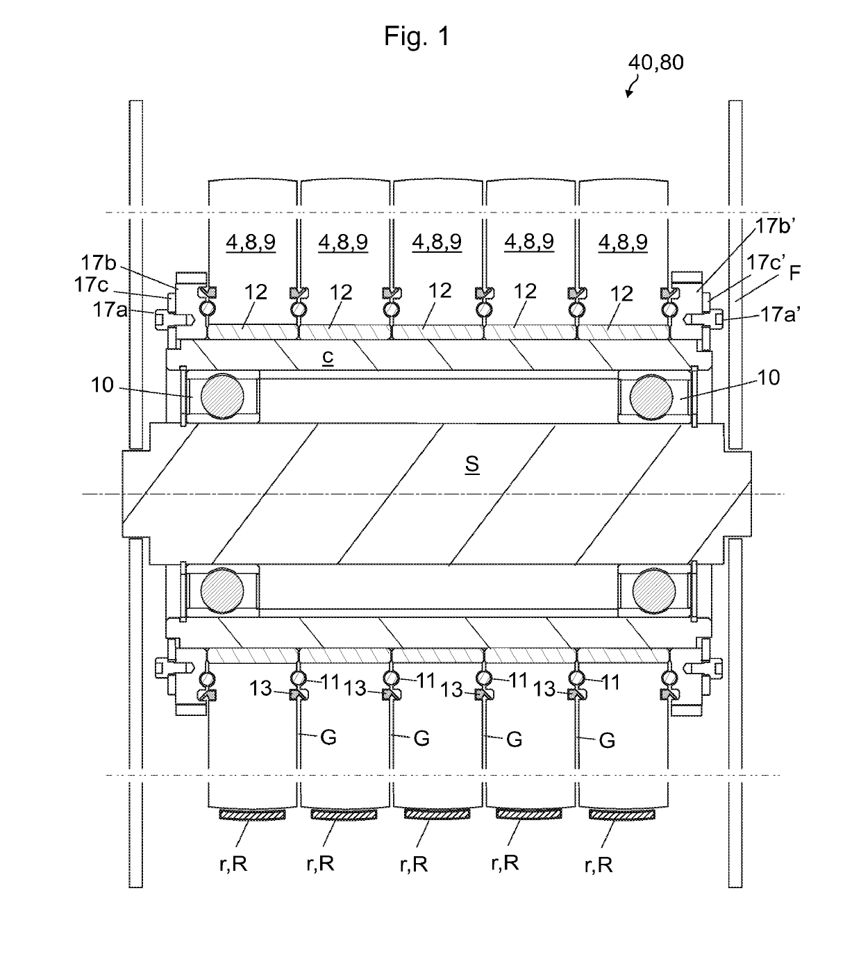
[0059]FIG. 1 illustrates a preferred embodiment of a rope wheel assembly 40,80 of an elevator according to the invention. The rope wheel assembly 40,80 comprises a frame F for being mounted on a structure of an elevator arrangement, a plurality of rope wheels 4,8,9 for guiding ropes of the elevator, and plurality of bearings 10-12, wherein the rope wheels 4,8,9 are mounted coaxially on the frame F via the bearings 10-12 such that they are rotatable relative to the frame F as well as relative to each other. The rope wheels 4,8,9 are non-driven rope wheels.

[0060]The rope wheel assembly 40,80 comprises a central shaft S passing through said rope wheels 4,8,9. The central shaft S is non-rotatable relative to the frame F, and the rope wheel assembly 40,80 comprises a hollow cylinder c surrounding the central shaft S, the hollow cylinder c being mounted on the central shaft S rotatably relative to the central shaft S. Thus, the rope wheels through which it passes can rotate together with ...


PUM


Abstract

A rope wheel assembly of an elevator includes a frame, a plurality of rope wheels for guiding ropes of the elevator, and a plurality of bearings. The rope wheels are mounted coaxially on the frame such that they are rotatable relative to the frame as well as relative to each other. The rope wheel assembly includes a central shaft passing through the rope wheels, which central shaft is non-rotatable relative to the frame, and the rope wheel assembly includes a hollow cylinder surrounding the central shaft, the hollow cylinder being mounted on the central shaft rotatably relative to the central shaft, each said rope wheel being mounted on the cylinder rotatably relative to the cylinder. The rope wheel assembly includes a bearing axially between rope wheels that are next to each other via which bearing they are supported on each other in axial direction. A compensator and an elevator arrangement implementing the rope wheel assembly are also disclosed.

Description

FIELD OF THE INVENTION[0001]The invention relates to guiding of ropes of an elevator by aid of rope wheels, the elevator being an elevator for transporting passengers and / or goods.BACKGROUND OF THE INVENTION[0002]An elevator typically comprises an elevator car and a counterweight, which are vertically movable in a hoistway. These elevator units are typically interconnected by ropes (later referred to as upper ropes) that suspend these elevator units on opposite sides of one or more rope wheels mounted higher than the elevator units. For providing force for moving the suspension ropes, and thereby also for the elevator units, one of the wheels is typically a drive wheel engaging the upper ropes. In addition to the upper ropes, the elevator may need to be interconnected by ropes which hang from the elevator car and the counterweight, and pass around rope wheels of a device (often referred to as a compensator) mounted at a stationary location which is lower than the elevator car and co...

Claims


Application Information

Patent Timeline
Patent Type & Authority Applications(United States)
IPC IPC(8): B66B15/02B66B7/06F16H55/56F16H55/50F16H57/04F16C19/14F16C33/66
CPCB66B15/02B66B7/068F16H55/56F16H55/50F16H57/0471F16C19/14F16C33/6637B66B7/02B66B7/10B66B7/1253B66B9/00B66B11/008B66B15/04B66D3/08
Inventor SALMI, MARKUS
Owner KONE CORP
Why Eureka
Try Eureka