Guide rail alignment method and arrangement

a technology for installing elevator guide rails and alignment methods, which is applied in the direction of mine lifts, transportation and packaging, etc., can solve the problems of time-consuming and time-consuming alignment, offset dimensions which need to be interpreted and re-calculated, and dedicated devices which are cumbersome to operate, etc., to speed up the alignment process, improve the final installation quality, and increase the accuracy of alignmen

Active Publication Date: 2019-04-11
KONE CORP
View PDF0 Cites 12 Cited by
  • Summary
  • Abstract
  • Description
  • Claims
  • Application Information

AI Technical Summary

Benefits of technology

[0013]The method and the arrangement according to the present disclosure may offer at least one of the following advantages over prior art.
[0014]The use of a combination of a light source on the vertically moveable base and a target member removably attached to the guide rail increases alignment accuracy thus improving final installation quality. The light source and the positioning of the target member allow the direct measurement of guide rail position, and no offset to a light source needs to be taken into account, since sling components or other equipment present in the elevator shaft are avoided by the positioning. This speeds up and simplifies the alignment process.
[0015]Determination of the correct guide rail direction is simplified as guide rail center may be used to acquire the alignment target. In prior art, offset dimensions which need to be interpreted and re-calculated are a source of potential mistakes. In the method and arrangement according to the present disclosure, they can be avoided making the verification of alignment more straightforward and thus more reliable.
[0016]In the method, the light source is always at the level of the previously aligned guide rail section. Such distances are especially suited to the accuracy of the light source. This further increases the improvement in quality.
[0017]As the positioning light source is on the vertically moveable base, it can be protected from the environment by the base structures and / or by a cover that can be used when the light source is not in use. This avoids damage to the positioning light source by dust or welding slag that may be present in the elevator shaft during installation work. This again, may increase the lifetime of the light source.

Problems solved by technology

Drawbacks of the current solutions are that the alignment contains multiple manual steps which is time-consuming, or dedicated devices which are cumbersome to operate.
The work needs to be performed accurately and trained personnel is needed, which can create a bottleneck in the construction of an elevator.
In prior art, offset dimensions which need to be interpreted and re-calculated are a source of potential mistakes.
This again, may increase the lifetime of the light source.

Method used


Image

  • Guide rail alignment method and arrangement
  • Guide rail alignment method and arrangement
  • Guide rail alignment method and arrangement

Examples


Embodiment Construction

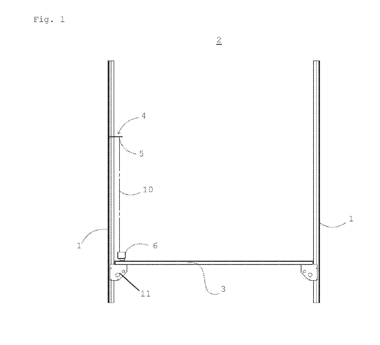
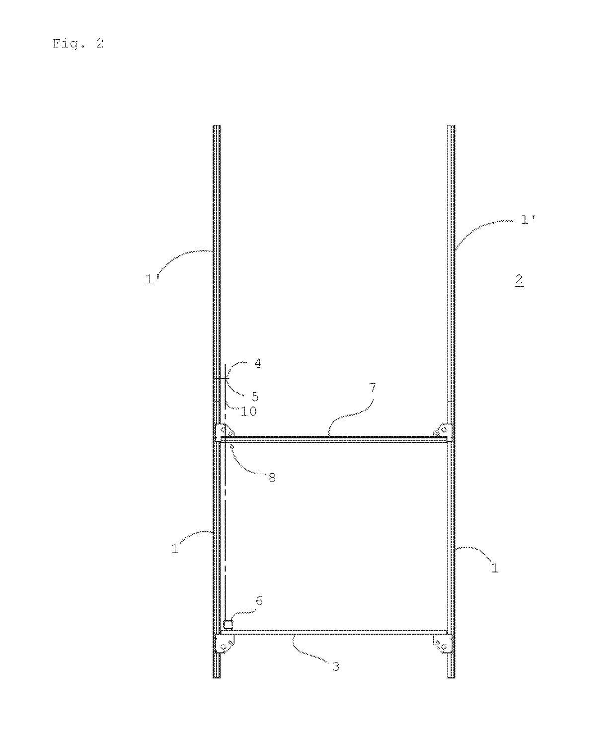
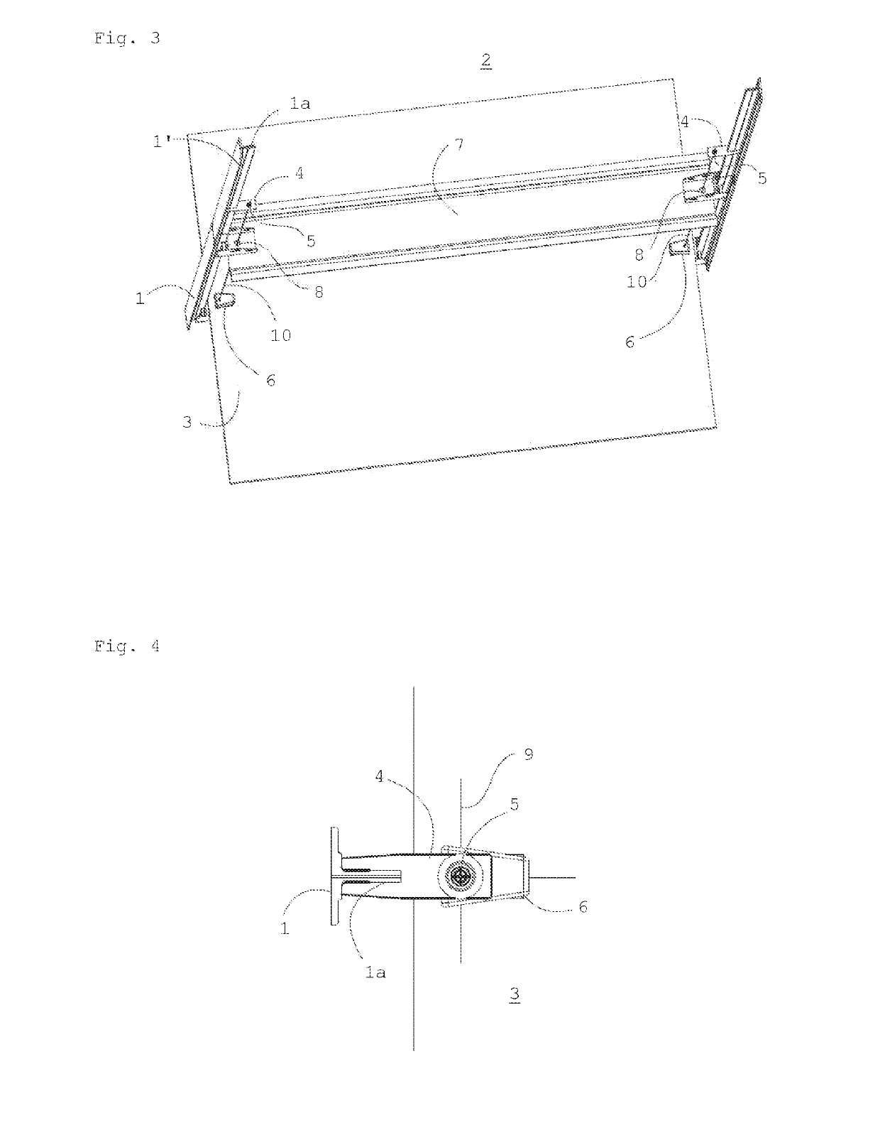
[0023]In one aspect, a guide rail alignment method is disclosed. The method comprises attaching and aligning a first pair of elevator car guide rail sections in an elevator shaft and mounting a vertically moveable base between the guide rail sections. The first pair of guide rail sections may be the first pair of guide rail sections to be installed in the elevator shaft. However, in the context of the current disclosure, the first pair of guide rail sections means the first pair that is used in the current method. It is thus possible that one or more pairs of guide rail sections have been installed previously.

[0024]The vertically moveable base means a surface that is moveable along the installed guide rails and can accommodate the positioning light source. The vertically moveable base thus follows the path of the elevator car in the final construction. By vertically moveable is herein meant that the movement of the base has a vertical component. The movement can thus deviate from ve...


PUM


Abstract

The current disclosure relates to a guide rail alignment method comprising attaching and aligning a first pair of elevator car guide rail sections in an elevator shaft and mounting a vertically moveable base between the guide rail sections. After the first pair of elevator car guide rail sections has been aligned, a target member comprising a target point is removably attached to a guide rail section, and a positioning light source able to produce a beam of collimated light is attached to the vertically moveable base, so that a beam of collimated light emitted in a predetermined direction by the positioning light source meets the target point of the target member. The position of the light source is then used to align a guide rail section of a second pair of guide rail sections. The current disclosure further relates to an elevator guide rail alignment arrangement.

Description

[0001]This application claims priority to European Patent Application No. EP171954951 filed on Oct. 9, 2017, the entire contents of which are incorporated herein by reference.TECHNICAL FIELD[0002]The present disclosure relates to installation of elevator guide rails. It especially relates to a guide rail alignment method during guide rail installation and to an arrangement for aligning guide rails.BACKGROUND ART[0003]Guide rails are used to guide the vertical movement of an elevator car in an elevator shaft. Usually there are two guide rails on the opposite walls of the elevator shaft and the elevator car is located between them and linked to the guide rails through guide shoes or guide rollers facing the guide rails. Guide rails are constructed from multiple guide rail sections that are connected to each other from their vertical ends to form a continuous guiding structure for the elevator. The guide rails are attached to the walls of the elevator shaft or other structures surround...

Claims


Application Information

Patent Timeline
Patent Type & Authority Applications(United States)
IPC IPC(8): B66B19/00
CPCB66B19/002B66B19/00
Inventor BARNEMAN, HAKAN
Owner KONE CORP
Why Eureka
Try Eureka