

A cooker
a technology for cookers and ovens, applied in the field of cookers, to achieve the effect of enhancing the sealing performance of the seal
- Summary
- Abstract
- Description
- Claims
- Application Information
AI Technical Summary
Benefits of technology
Problems solved by technology
Method used
Image

Examples
first embodiment
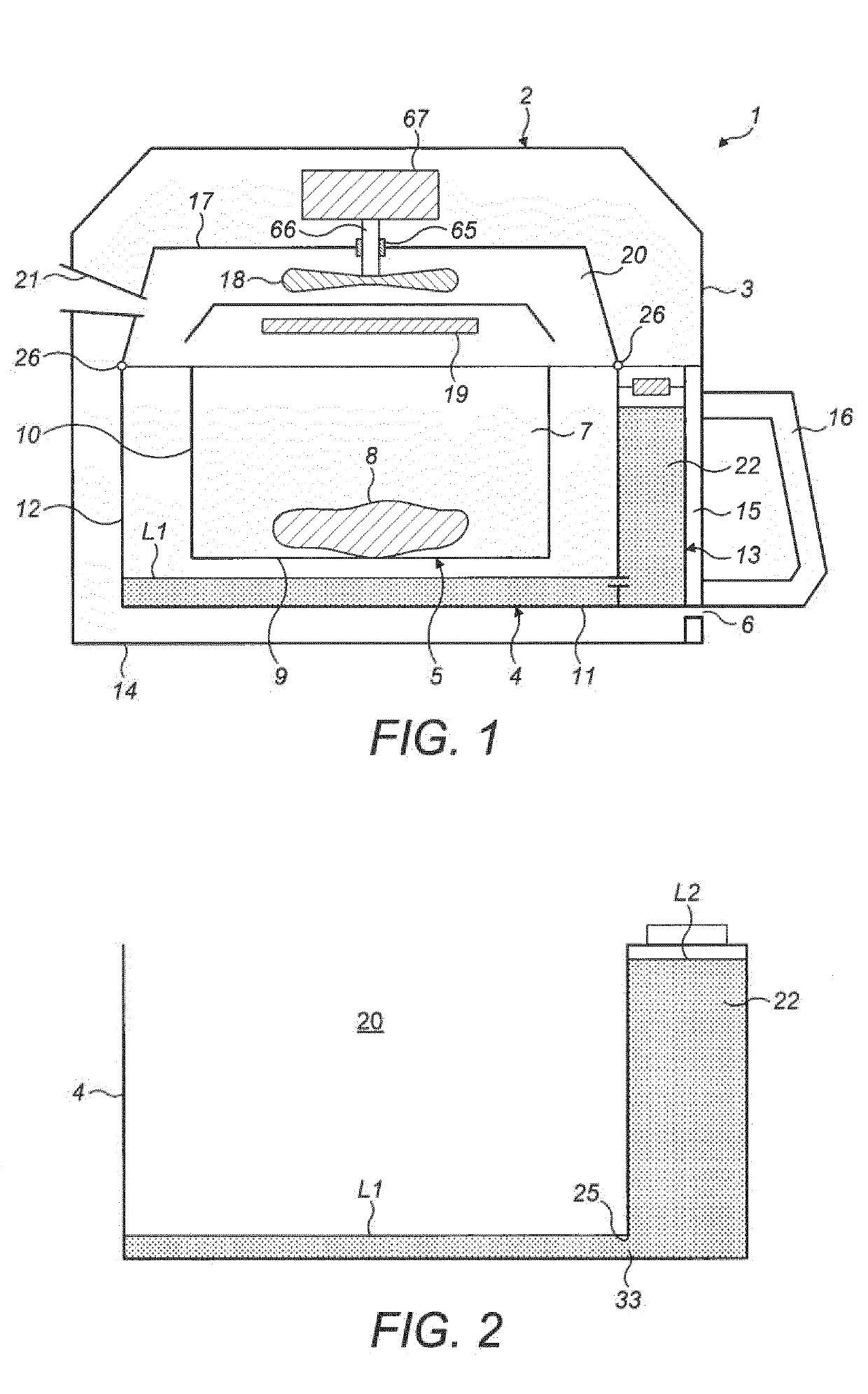
[0060]FIG. 2 shows system 13. The system 13 comprises a water reservoir 22 in fluid communication with the cooking chamber 20, for simplification the upper enclosure 17, fan 18 and heater 19 are not shown. The water reservoir 22 is configured to retain water at a higher level L2 than the predetermined level L1 of water in the bottom of the cooking chamber 20 for steam generation, the water level difference being maintained by a vacuum pressure above the water in the reservoir 22. The water reservoir 22 is disposed adjoining the cooking chamber 20 so that the water reservoir 22 and the cooking chamber 20 share a common wall. An opening 33 is provided in the common wall so that the reservoir 22 is in fluid communication with the cooking chamber 20. An upper edge 25 of the opening is coincident with the predetermined level L1, in other words it is coincident with the desired water level in the bottom of the cooking chamber 20. Therefore, if the required predetermined level L1 is 1 cm, ...
second embodiment
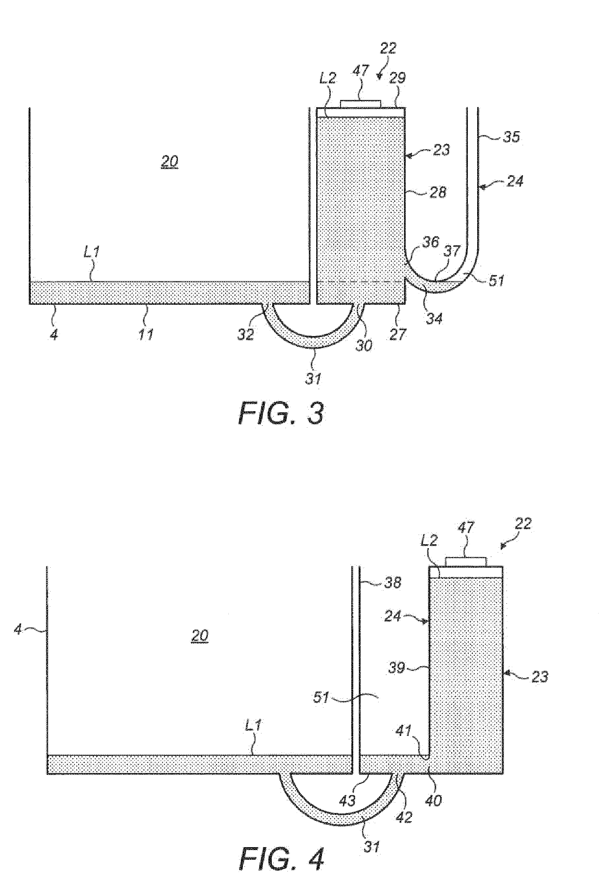
[0066]In the invention shown in FIG. 3, the tank 23 comprises a base 27 and a wall 28 upstanding around the base 27 to form the sides of the tank 23, a top wall 29 extends across upper edges of the wall 28 to enclose the tank 23 at its top end. An opening 30 is provided in the bottom of the tank 23 which is connected by a channel 31 that extends from the opening 30 in the tank 23 to a corresponding opening 32 in the base 11 of the cooking chamber 20 to fluidly connect the cooking chamber 20 to the tank 23.
[0067]An opening is provided in the top wall 29 of the tank 23 through which the tank 23 can be filled with water. The opening is sealable by any conventional means. For example a screw cap 47 could be used to seal the tank 23, wherein the tank 23 comprises a corresponding threaded section around the opening for the screw cap 47 to attach to. Alternatively, the opening may be a plain opening and a rubber or polymer bung is provided to insert into the opening to seal the opening.
[00...
third embodiment
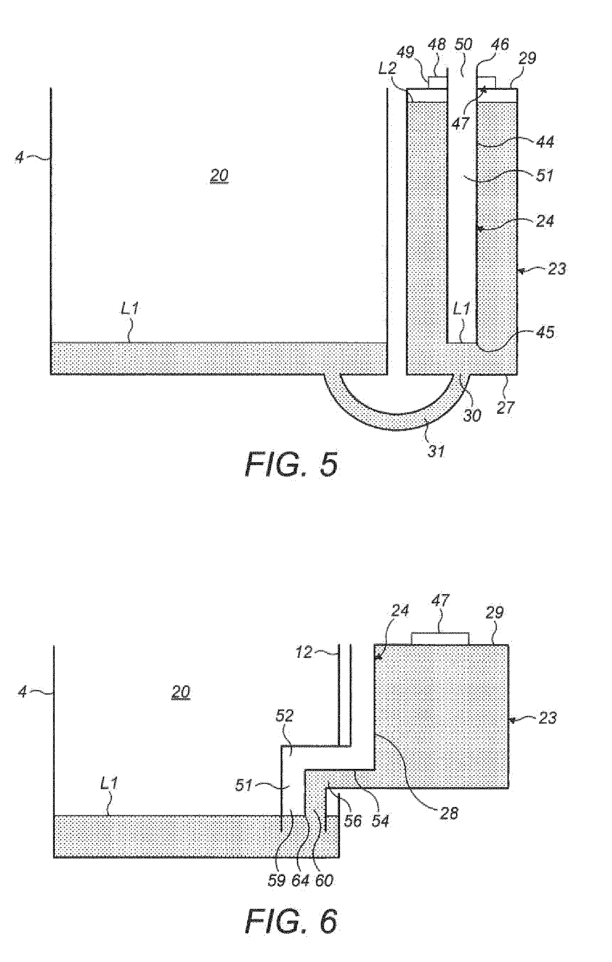
[0074]Referring now to FIG. 4, the invention is shown wherein like features retain the same reference numbers. In this embodiment the reservoir comprises a divider 39 to partition the reservoir 22 into the breather 24 and the tank 23 so that the breather 24 and the tank 23 form separate chambers within the reservoir 22. An opening 40 is provided in the divider 39 so that the tank 23 is in fluid communication with the breather 24. The breather 24 is open to atmosphere to define the air path into the tank 23.
[0075]A lower end 41 of the divider forms an upper edge 41 of the opening 40 between the tank 23 and the breather 24 which is coincident with the predetermined level L1, in other words it is coincident with the desired water level in the bottom of the cooking chamber 20.
[0076]The channel 31 connecting the reservoir 22 to the cooking chamber 20 connects to an opening 42 in a base wall 43 of the reservoir 22. Although in the illustrated embodiment the opening 42 is provided in the b...
PUM
 Abstract
Description
Claims
Application Information