High coverage battery usage monitor

a multi-cell battery and monitoring device technology, applied in battery/fuel cell control arrangement, secondary cell servicing/maintenance, instruments, etc., can solve the problem that existing solutions fail to fully account for the individual operating conditions of each of the battery cells, and achieve the effect of improving battery performance and useful life, optimizing battery performance, and maintaining battery safety

Inactive Publication Date: 2019-04-18
NEAPCO INTPROP HLDG LLC
View PDF0 Cites 7 Cited by
  • Summary
  • Abstract
  • Description
  • Claims
  • Application Information

AI Technical Summary

Benefits of technology

[0005]The subject disclosure includes a monitoring and control method for monitoring and controlling a multi-cell battery. More specifically, the subject disclosure provides for complete monitoring of battery cells in a high-cell-count battery. The subject disclosure also provides for using high-coverage data regarding the battery cells to improve operation, diagnostics, and prognostics of the multi-cell battery.
[0020]Optimization of battery performance and maintaining battery safety often hinges on not overstressing the weakest battery cell in a multi-cell battery, therefore monitoring at the cell level is preferred. By monitoring every individual battery cell, the battery operation can be tailored to avoid damaging the weakest battery cells and therefore improve battery performance and useful life. Individual battery cell monitoring also improves battery safety by identifying cell voltage, current or temperature issues before a cell failure occurs.

Problems solved by technology

However, existing solutions fail to fully account for the individual operating conditions of each of the battery cells within a multi-cell battery in order to control use of the battery cells within the cell operating limits and in accordance with an optimal usage profile as determined by a calibrated cell model for each of the battery cells.

Method used


Image

  • High coverage battery usage monitor
  • High coverage battery usage monitor
  • High coverage battery usage monitor

Examples


Embodiment Construction

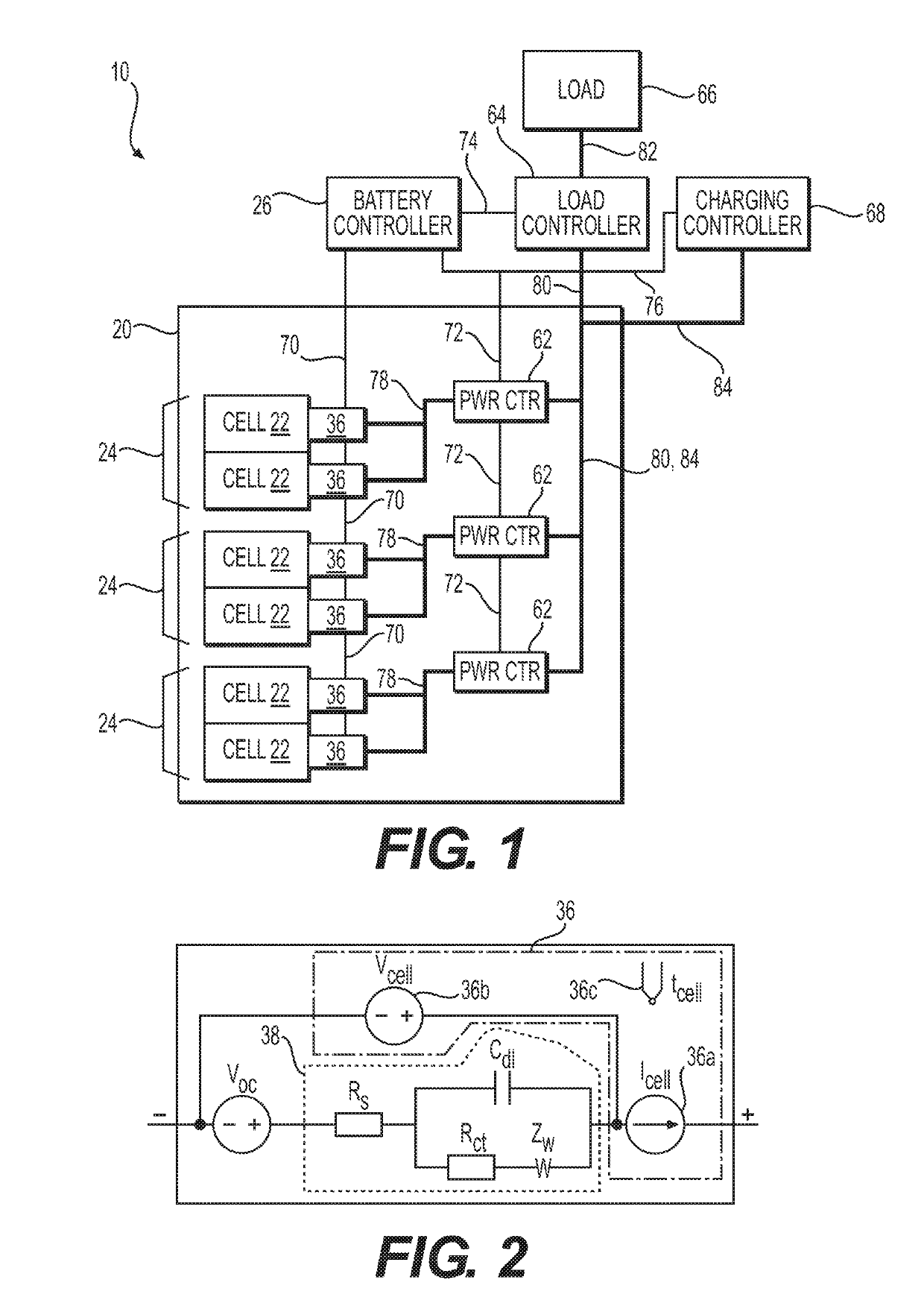
[0032]Referring to the Figures, wherein like numerals indicate corresponding parts throughout the several views, a method 100 and system 10 for monitoring and controlling a multi-cell battery 20 including a plurality of battery cells 22 is provided.

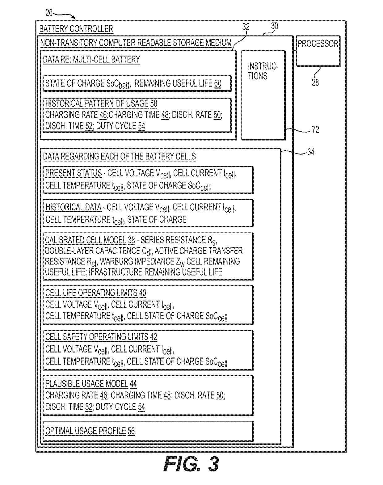
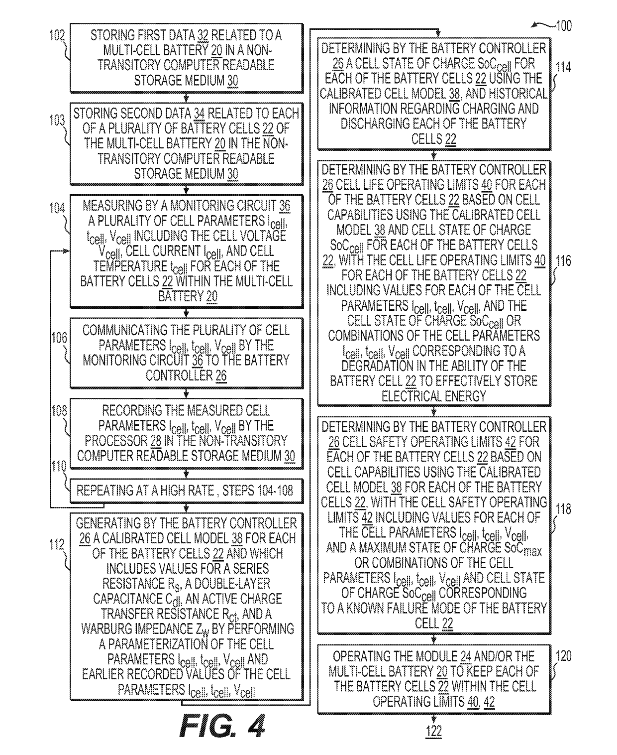
[0033]The monitoring and control method 100 for monitoring and controlling a multi-cell battery 20 begins with the step of 102 providing a battery controller 26 including a processor 28 and a non-transitory computer readable storage medium 30 storing battery data 32 related to the multi-cell battery 20 and storing cell data 34 including information related to each of the battery cells 22. One or more of the battery cells 22 may be functionally combined as a module 24. In other words, a module 24 is a subset of the battery cells 22 in the multi-cell battery 20 which are connected in such a way that the parameters can be measured for the module 24 alone. An overview of the system 10 is shown in the block diagram of FIG. 1. FIG. 2 is a schem...


PUM

PropertyMeasurementUnit
electrical currentaaaaaaaaaa
series resistanceaaaaaaaaaa

Abstract

A method and system for monitoring and controlling a multi-cell battery including a plurality of battery cells uses a battery controller having a processor and a non-transitory computer readable storage medium. A monitoring circuit including current, voltage, and temperature sensors measures a plurality of cell parameters for each of the battery cells, which are communicated to the battery controller. The battery controller performs a parameterization of the cell parameters and past values of the cell parameters to generate a calibrated cell model for each of the battery cells. An optimal usage profile is determined for each of the battery cells as an optimized compromise of cell operating limits between different battery cells within the multi-cell battery, and then causes each of the battery cells to be operated according to the corresponding optimal usage profile. Calculating and reporting of the remaining useful life of the battery is also provided.

Description

CROSS REFERENCE TO RELATED APPLICATION[0001]This U.S. utility patent application claims the benefit of U.S. provisional patent application No. 62 / 572,734, filed Oct. 16, 2017, the contents of which are incorporated herein by reference in its entirety.BACKGROUND OF THE INVENTION1. Field of the Invention[0002]A system and method for monitoring and controlling a multi-cell battery.2. Description of the Prior Art[0003]Several different types of systems and methods for monitoring and controlling a multi-cell battery exist today. Such systems generally include a controller to cause battery cells within a multi-cell battery to be charged and discharged evenly. It is also known in the art to estimate and preserve battery life based on general usage patterns of the battery.[0004]However, existing solutions fail to fully account for the individual operating conditions of each of the battery cells within a multi-cell battery in order to control use of the battery cells within the cell operatin...

Claims


Application Information

Patent Timeline
Patent Type & Authority Applications(United States)
IPC IPC(8): B60L11/18G01R31/36H01M10/42H01M10/48
CPCB60L11/1857B60L11/1862H01M10/425G01R31/3648B60L2240/549G01R31/396B60L2240/547B60L2240/545H01M10/482G01R31/382H01M2010/4271H01M10/48G01R31/367B60L58/13B60L58/16Y02T90/16Y02T10/70Y02E60/10
Inventor REMBOSKI, DONALDDEDO, JACQUELINE
Owner NEAPCO INTPROP HLDG LLC
Why Eureka
Try Eureka