Method and device for monitoring a drive of a drive system of a motor vehicle

A drive system, drive device technology, applied in the direction of control device, engine control, machine/engine, etc., can solve the problem of identification, inertia monitoring, can not use gasoline engine meaningfully, ignore it, etc.

Active Publication Date: 2016-12-21
ROBERT BOSCH GMBH
View PDF5 Cites 0 Cited by
  • Summary
  • Abstract
  • Description
  • Claims
  • Application Information

AI Technical Summary

Problems solved by technology

Defects in such compensating mechanisms cannot be reliably detected by torque monitoring and require separate monitoring
[0012] Due to the requirements in terms of exhaust gas aftertreatment, fuel injection occurs more and more often during the coasting of gasoline engines, so that conventional inertia monitoring cannot be meaningfully used in gasoline engines
Rather, such an injection likewise does not constitute a relevant drive torque, since the energy of the injected fuel is dissipated as a hot exhaust gas flow without a change in torque, but this is not possible during inertial monitoring. ignore this extra injection volume

Method used


Image

  • Method and device for monitoring a drive of a drive system of a motor vehicle
  • Method and device for monitoring a drive of a drive system of a motor vehicle

Examples


Embodiment Construction

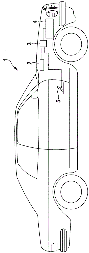
[0043] figure 1 A schematic illustration of a motor vehicle 1 is shown with a monitoring device 2 for monitoring faults in the drive system, for example, faults in the motor control system. The monitoring device is connected to a motor controller 3 , which activates the drive motor 4 . As the drive motor 4, every possible power machine is considered, such as a diesel engine, a petrol engine, an electric motor, a gas engine and the like.

[0044] Furthermore, the motor control unit 3 is connected to the accelerator pedal 5 for registering information about the position of the accelerator pedal and assigning it the driver's desired torque. Furthermore, motor control unit 3 is designed to activate drive motor 4 as a function of the driver's desired torque, so that it provides a drive torque for propelling motor vehicle 1 that substantially corresponds to the driver's desired torque.

[0045] The monitoring device 2 is primarily used to monitor the drive of the drive motor during ...


PUM


Abstract

The method involves determining whether a motor car (1) is in an overrun condition, where a drive of the motor car does not provide drive torque in the overrun condition. A temporal speed threshold value characteristic is determined based on a momentary vehicle speed and a preset detention of the motor car on a linear distance when the overrun condition is determined. An error is determined when the momentary vehicle speed present during the overrun condition exceeds a threshold value, which is predetermined by the threshold value characteristic. Independent claims are also included for the following: (1) a monitoring device for monitoring a drive system of a vehicle (2) a drive system of a vehicle comprising a drive motor (3) a computer program product comprising instructions for performing a method for monitoring a drive system of a vehicle on errors.

Description

technical field [0001] The invention relates to a drive system for a motor vehicle, in particular to a method for monitoring faults of the drive that lead to undesired acceleration or deceleration of the motor vehicle. Background technique [0002] A large number of engine functions of the internal combustion engine are carried out in a motor controller which activates the internal combustion engine. Calculation errors, bit flips (bitkippers) and the like can produce false outputs in unsecured motor controllers, which can lead to damage in motor vehicles in severe cases A welcome acceleration, for example due to too high a fuel injection quantity, or an undesired deceleration, for example in the case of a hybrid drive due to the activation of an energy recuperation function. Since such faults can create situations that endanger persons in road traffic, it is necessary for the motor controller to independently detect such faults and place the motor vehicle in a safe state. ...

Claims


Application Information

Patent Timeline
Patent Type & Authority Patents(China)
IPC IPC(8): B60W50/02F02D41/04F02D41/12F02D41/22B60W30/18
CPCB60W30/18136B60W50/0205B60W2030/18081B60W2520/10B60W2552/15B60W2552/40F02D41/045F02D41/12F02D41/22F02D2200/501F02D2200/602F02D2200/702Y02T10/60
Inventor S.策尔马克E.伯格曼J.里希特
Owner ROBERT BOSCH GMBH
Why Eureka
Try Eureka