
Wind Turbine Comprising a Yaw Bearing System

a technology of yaw bearings and wind turbines, which is applied in the direction of bearing repair/replacement, sliding contact bearings, machines/engines, etc., can solve the problems of time-consuming, difficult to handle, and high manufacturing cost of passive systems, so as to reduce service costs and total service time, quick and simple replacement, good adhesion properties

Active Publication Date: 2019-04-18
ENVISION ENERGY DENMARK
View PDF2 Cites 6 Cited by
  • Summary
  • Abstract
  • Description
  • Claims
  • Application Information

AI Technical Summary

Benefits of technology

The invention provides a yaw bearing system that is stronger and more durable than previous versions. The system includes an adjusting mechanism and a new lower pad that can be bonded to the support element using an adhesive. The adhesive has good adhesion properties to the materials used for the lower pad and the support element, reducing service costs and time. The technical effect is an improved yaw bearing system that is more durable and reliable.

Problems solved by technology

Such passive systems are often configured as large and heavy units which are difficult to handle.
Such passive systems are also expensive to manufacture and are costly and time consuming to service.
This is time consuming and adds to the total service costs.
These fixing elements further add to the complexity and costs of the bearing units.
The roller elements require regular maintenance to prevent blockage of their rotating motion which adds to the total service costs.
Secondly, the calliper structure requires complex machining in order to enable the mounting of the roller elements which, in turn, adds to the total costs of the bearing units.
The use of roller elements requires regular maintenance and complex machining of the calliper structure as mentioned above.
The ring-shaped calliper structure forms a large and heavy item which is difficult to handle and increases the total weight of the bearing unit.
This increases the risk of the radial pad being squeezed out during yawing and of the flange edge rubbing against the bolt heads potentially breaking off the bolt heads.

Method used


Image

  • Wind Turbine Comprising a Yaw Bearing System
  • Wind Turbine Comprising a Yaw Bearing System
  • Wind Turbine Comprising a Yaw Bearing System

Examples


first embodiment

[0089]FIG. 5 shows a method for replacing the radial pad according to the invention,

second embodiment

[0090]FIG. 6 shows the method for replacing the radial pad,

[0091]FIG. 7 shows a method for replacing the lower pad according to the invention,

[0092]FIG. 8 shows a cross-sectional view of a first embodiment of the yaw bearing unit according to the invention, and

[0093]FIG. 9 shows a cross-sectional view of a second embodiment of the yaw bearing unit according to the invention.

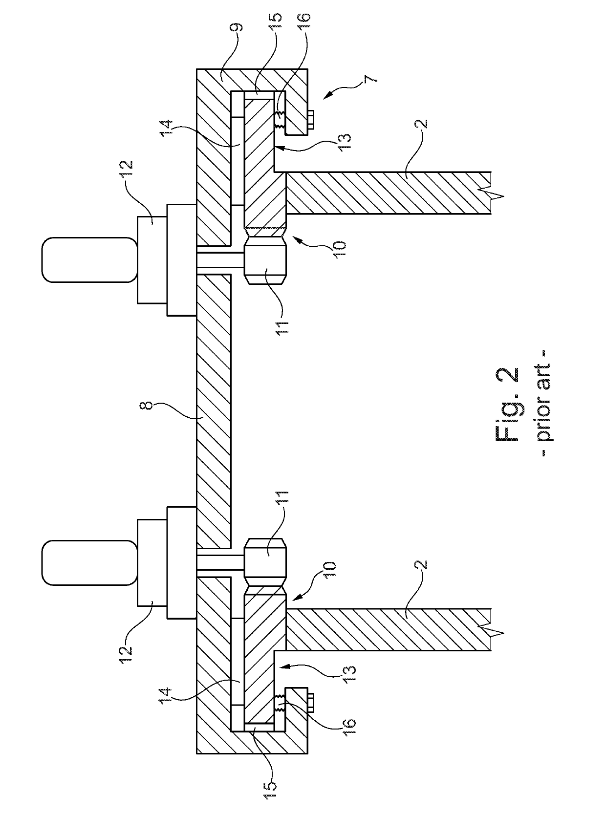
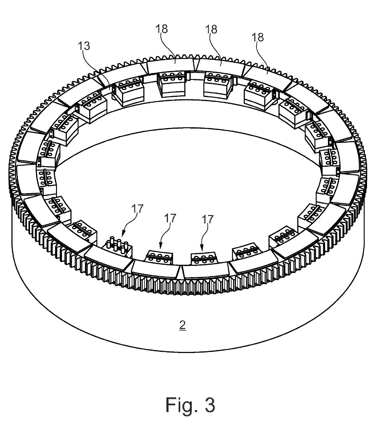
[0094]In the following text, the figures will be described one by one, and the different parts and positions seen in the figures will be numbered with the same numbers in the different figures. Not all parts and positions indicated in a specific figure will necessarily be discussed together with that figure.


PUM


Abstract

The invention relates to a wind turbine comprising a plurality of individual yaw bearing units and a method of replacing a pad of such a yaw bearing unit. The yaw bearing unit comprises a calliper structure divided into an upper portion and a lower portion, wherein the lower portion can be dismounted without also dismounting the upper portion. An upper pad is provided between a flange providing support for a nacelle and a mainframe of the nacelle. A radial pad is arranged on a radial surface of the upper portion and contacts a stop element located at either ends of the upper portion. An adjustable lower pad is arranged in a through hole in the lower portion and can be replaced via a lower opening in the lower portion. The radial pad can be replaced in a sideward direction by removing one of the stop elements or replacing it in an axial direction by removing the lower portion.

Description

FIELD OF THE INVENTION[0001]The present invention relates to a wind turbine comprising a wind turbine tower, a nacelle with a mainframe, and a ring gear and a flange arranged on the wind turbine tower, the ring gear being configured to engage at least one drive unit configured to yaw the nacelle relative to the wind turbine tower, wherein the mainframe is slidable supported on the flange by a plurality of individual yaw bearing units arranged relative to each other, the yaw bearing unit comprising a yaw calliper structure configured to be mounted to the mainframe, wherein an upper pad is arranged between the mainframe and the flange, and wherein a radial pad and a lower pad project from the calliper structure and contact the flange.BACKGROUND OF THE INVENTION[0002]The method of using a yaw sliding bearing system when yawing the nacelle relative to the wind turbine tower, wherein the mainframe of the nacelle is slidable supported by a flange provided at the top of the wind turbine to...

Claims


Application Information

Patent Timeline
Patent Type & Authority Applications(United States)
IPC IPC(8): F03D80/70F16C17/03
CPCF03D80/70F16C17/03F05B2230/80F03D7/0204F16C17/10F16C33/26F16C2360/31F16C2237/00F16C25/04Y02E10/72F16C17/26F16C17/107
Inventor SORENSEN, CARSTEN BENDIX
Owner ENVISION ENERGY DENMARK
Learn More