User terminal, radio base station and radio communication method

a radio communication method and user terminal technology, applied in the direction of wireless communication, network data management, electrical equipment, etc., can solve the problem of limited spectra of licensed bands, and achieve the effect of adequately transmitting uci

Inactive Publication Date: 2019-04-18
NTT DOCOMO INC
View PDF10 Cites 19 Cited by
  • Summary
  • Abstract
  • Description
  • Claims
  • Application Information

AI Technical Summary

Benefits of technology

[0013]According to the present invention, it is possible to transmit UCI adequately, at a desired timing in a carrier where LBT is configured.

Problems solved by technology

Although more frequency bands need to be added to accommodate this increasing user traffic, licensed bands have limited spectra (licensed spectra).

Method used


Image

  • User terminal, radio base station and radio communication method
  • User terminal, radio base station and radio communication method
  • User terminal, radio base station and radio communication method

Examples


first embodiment

[0067]According to the first embodiment of the present invention, a UE reports information as to whether or not the UE supports transmission in PUCCH format (PF: PUCCH Format) 4 and / or 5 (whether or not to support PF 4 / 5) in LAA SCells, to the network side (for example, eNB), as terminal capability information (UE capability).

[0068]This capability information here may be reported using one or a combination of the following: (1) Existing UE capability information bits (capability bits) to indicate that PF 4 / 5 are supported (these bits may be included and reported in, for example, PhyLayerParameters-v13x0, which is specified as a parameter for LTE Rel. 13); (2) New UE capability information bits to indicate that PF 4 / 5 are supported in LAA SCells (these bits may be included, for example, in PhyLayerParameters-v14x0, which is defined as a parameter for LTE Rel. 14, and reported as UL-LAA-specific information); (3) L-LAA UE capability information, including capability information to ind...

embodiment 2.1

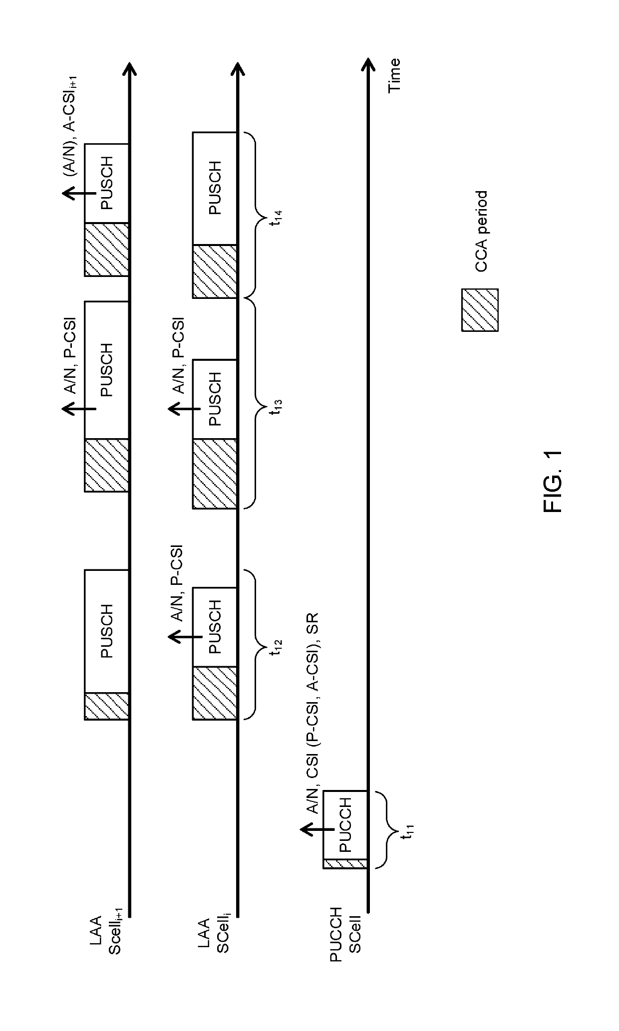
[0078]FIG. 1 is a diagram to explain the UCI transmission operation according to embodiment 2.1. FIG. 1 illustrates three LAA SCells. “PUCCH SCell” is an LAA SCell that is capable of PUCCH transmission (configured as a PUCCH cell). “LAA SCelli” and “LAA SCelli+1” are LAA SCells that cannot perform PUCCH transmission (not configured as PUCCH cells). Assume that the SCell index of LAA SCelli is smaller than that of either LAA SCelli+1 or the PUCCH SCell. Note that application of this embodiment is not limited to the case where a UE uses three LAA SCells.

[0079]In FIG. 1, a UE executes listening in the CCA period before transmitting UL signals in each SCell, and, upon judging that the channel is idle, the UE carries out UL transmission. In addition, periods t11 to t14 illustrated in FIG. 1 are simply exemplary periods for explaining the UCI transmission operation, and the order these periods occur, the length of these periods and so on are not limited.

[0080]At a timing (for example, a T...

embodiment 2.2

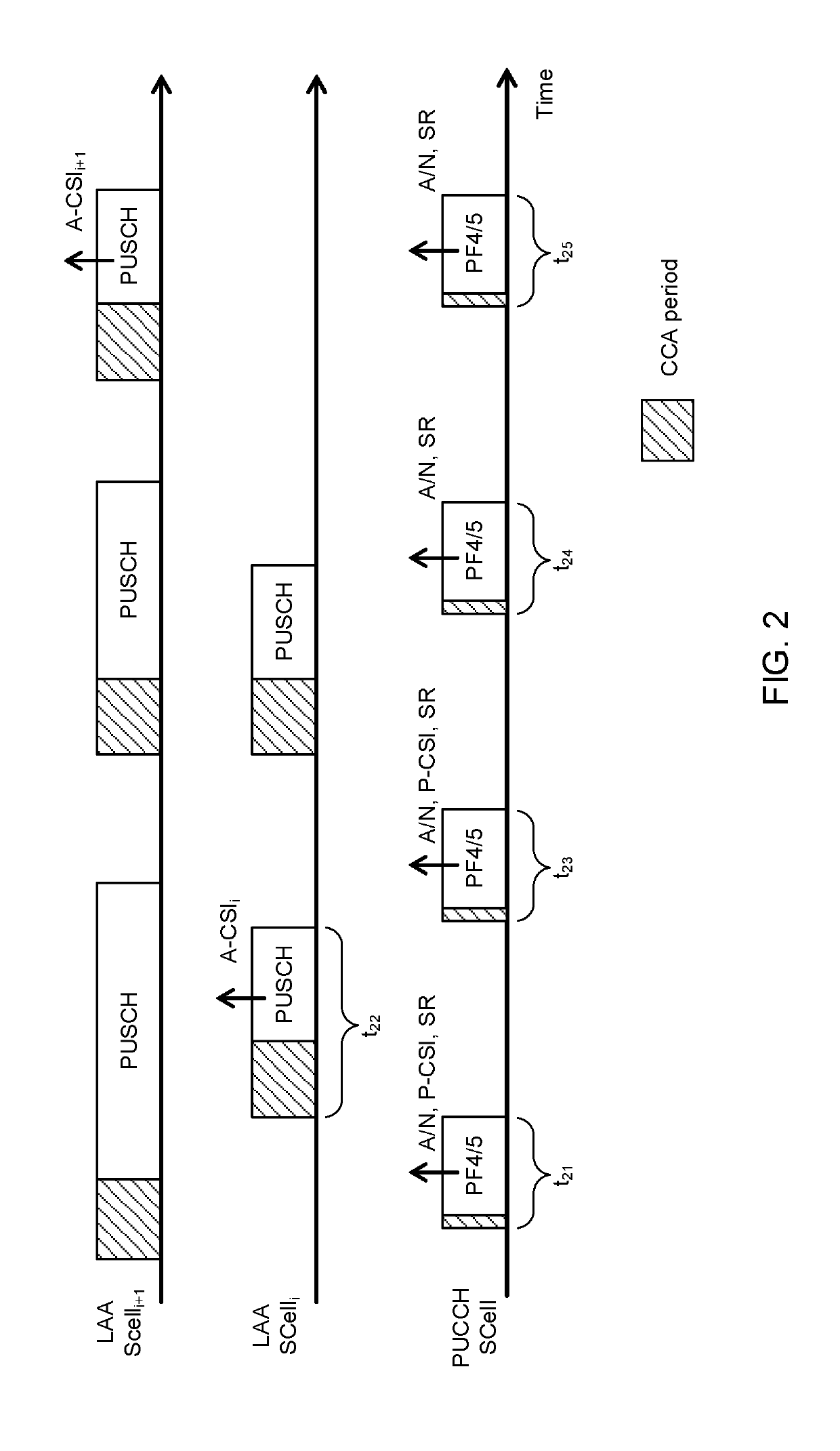
[0087]FIG. 2 is a diagram to explain the UCI transmission operation according to embodiment 2.2. FIG. 2 illustrates a similar example to FIG. 1.

[0088]At a timing where at least one of A / N, P-CSI and SR should be transmitted (for example, TTI), the UE transmits the UCI based on the LBT in the PUCCH on the LAA SCell (PUCCH SCell) (illustrated as t21, t23, t24 and t25).

[0089]FIG. 2 illustrates an example in which the UE transmits PUCCH in PF 4 / 5 in LAA SCells, but different PFs may be used as well. Note that at a timing where only one P-CSI is transmitted in PUCCH, the UE may transmit this one P-CSI in PF 4 and / or 5, or transmit this one P-CSI in an existing PF (for example, PF 2).

[0090]At a timing where A-CSI is triggered (A-CSI is transmitted), the UE transmits A-CSI based on LBT using the PUSCH of the triggered cell (exemplified at t22 and t25). For example, at t22, A-CSI (A-CSIi) for LAA SCelli is transmitted in LAA SCelli.


PUM


Abstract

The present invention is designed to suitably realize UCI (Uplink Control Information) transmission at a desired timing in a carrier where LBT (Listen Before Talk) is configured. A user terminal, according to one embodiment of the present invention, has a transmission section that transmits signals in carriers where listening is performed before uplink transmission, a receiving section that receives PUCCH cell configuration information as to whether or not at least one of the carriers is a cell where a PUCCH (Physical Uplink Control Channel) is transmitted, and a control section that controls the transmission of uplink control information (UCI) in the carriers based on the PUCCH cell configuration information.

Description

TECHNICAL FIELD[0001]The present invention relates to a user terminal, a radio base station and a radio communication method in a next-generation mobile communication system.BACKGROUND ART[0002]In the UMTS Universal Mobile Telecommunications System) network, the specifications of long-term evolution (LTE) have been drafted for the purpose of further increasing high speed data rates, providing lower delays and so on (see non-patent literature 1). Also, the specifications of LTE-A (also referred to as LTE-advanced, LTE Rel. 10, 11 or 12, etc.) have been drafted for further broadbandization and increased speed beyond LTE (also referred to as LTE Rel. 8 or 9), and successor systems of LTE (also referred to as, for example, FRA (Future Radio Access), 5G (5th generation mobile communication system), LTE Rel. 13 and so on) are under study.[0003]The specifications of Rel. 8 to 12 LTE have been drafted assuming exclusive operation in frequency bands that are licensed to operators (also refer...

Claims


Application Information

Patent Timeline
Patent Type & Authority Applications(United States)
IPC IPC(8): H04W8/22H04W16/14H04W74/08H04W72/14H04W72/04
CPCH04W8/22H04W16/14H04W74/0808H04W72/14H04W72/0413H04W72/0446H04W72/0453H04W74/006H04W72/23H04W72/21
Inventor HARADA, HIROKINAGATA, SATOSHILIU, LIUWANG, LIHUIJIANG, HUILING
Owner NTT DOCOMO INC
Why Eureka
Try Eureka