
Manufacturing Frame

Pending Publication Date: 2019-04-25
NIKE INC
View PDF2 Cites 2 Cited by
  • Summary
  • Abstract
  • Description
  • Claims
  • Application Information

AI Technical Summary

Benefits of technology

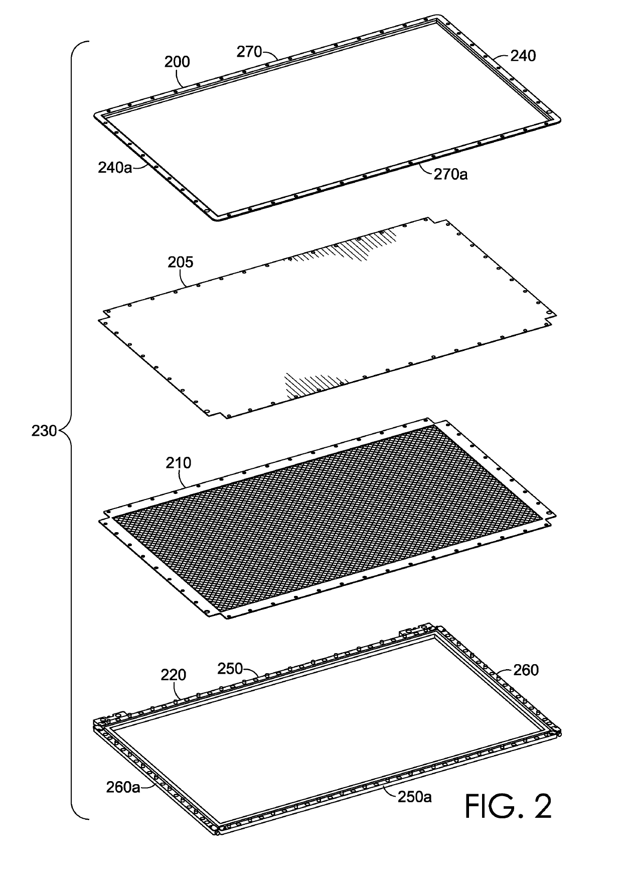
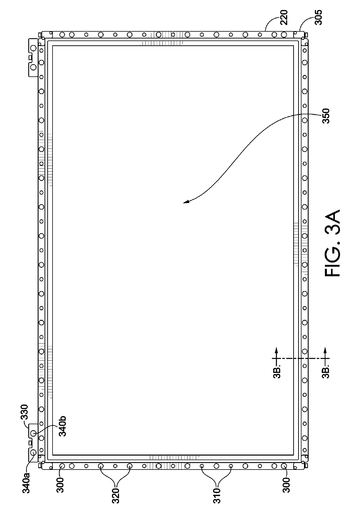
This disclosure is about a frame used to hold materials in place during manufacturing operations. The frame is designed to securely hold flexible materials at a desired tension and prevent changes in tension or position during manufacturing. The frame has an alignment tab that helps the manufacturing station know where the frame is located and where the materials on it are. This helps the manufacturing station start from a common position and continue with the sequential operations without having to re-inspect or reposition the materials. The alignment tab is easy to use without requiring visual inspection or repositioning of the materials. Overall, the frame improves the manufacturing process by facilitating the movement of materials between manufacturing stations and ensuring consistent tension and positioning of the materials.

Problems solved by technology

These systems are cumbersome, complicated, and, particularly with human operators, prone to variation, error, and the possibility of injury.

Method used


Image

  • Manufacturing Frame
  • Manufacturing Frame
  • Manufacturing Frame

Examples


Embodiment Construction

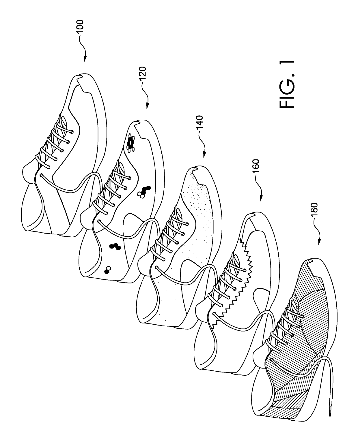
[0018]Working with flexible materials, such as non-woven materials, fabrics, and films, can be challenging during manufacturing. The materials can fold back on themselves or under themselves, drape in undesired ways, shift position, or otherwise thwart efforts to keep the parts in a particular spot or orientation during manufacturing. Movement of these materials can cause terminal defects in, for example, seams or joints between parts, cut lines, and aesthetics. For example, parts may be cut to the wrong shape or size if the material(s) are not positioned as intended relative to a cutting blade. As another example, a material in a stack of two or more materials might not be joined to any other material in the stack if the material has folded onto itself and does not pass under a sewing needle or quilting arm. An improperly positioned part that is glued or seamed out of position may be ugly or non-functional because of the misplacement.

[0019]Conventional efforts to maintain the posit...


PUM

PropertyMeasurementUnit
Lengthaaaaaaaaaa
Structureaaaaaaaaaa

Abstract

A manufacturing frame comprises one or more alignment tabs. Each alignment tab comprises an alignment element. The alignment element interacts with a corresponding alignment element at a manufacturing station to identify to the manufacturing station the position and orientation of the frame. The frame supports a flexible material in a known position and orientation relative to the frame, allowing the manufacturing station to infer the position and orientation of the flexible material on the frame from the interaction of the alignment elements on the frame and the manufacturing station.

Description

CROSS-REFERENCE TO RELATED APPLICATIONS[0001]This application having attorney docket number 316815 / 160352US02 and entitled “Manufacturing Frame” claims the benefit of priority of U.S. Provisional Application No. 62 / 576,600, entitled “Manufacturing Frame,” and filed Oct. 24, 2017. Additionally, this application is related by subject matter to U.S. patent application Ser. No. ______, entitled “Agile Manufacturing Processes and Systems,” having Attorney Docket Number 22752.316814 / 170323US01, which claims priority to U.S. Provisional Application No. 62 / 576,592, entitled “Agile Manufacturing Processes and Systems,” and filed Oct. 24, 2017. The entirety of the aforementioned applications are incorporated by reference herein.TECHNICAL FIELD[0002]This disclosure relates to a frame for supporting material during a manufacturing operation. More particularly, the present invention relates to a frame for supporting a flexible material during a series of manufacturing operations.BACKGROUND[0003]...

Claims


Application Information

Patent Timeline
IPC IPC(8): D06C3/08A43D8/00D06H7/00B26D7/02B26D7/01
CPCD06C3/08A43D8/003D06H7/00B26D7/025B26D7/015D10B2501/043A43B23/0245A43D8/00
Inventor BAGGEN, JAREDBARNEY, BRUCE ALANDEHAVEN, DANIEL B.KILGORE, BRUCE J.TERLIZZI, JOHN JOSEPH
Owner NIKE INC
Learn More