Blade and rotor for a turbomachine and turbomachine

Active Publication Date: 2019-04-25
MTU AERO ENGINES GMBH
View PDF0 Cites 6 Cited by
  • Summary
  • Abstract
  • Description
  • Claims
  • Application Information

AI Technical Summary

Benefits of technology

[0025]The object of the present invention is to better limit crack growth in the blades and rotors of turbomachines. Another object of the in

Problems solved by technology

In the case of a spread of the crack, either the crack growth potential is limited

Method used


Image

  • Blade and rotor for a turbomachine and turbomachine
  • Blade and rotor for a turbomachine and turbomachine
  • Blade and rotor for a turbomachine and turbomachine

Examples


Example

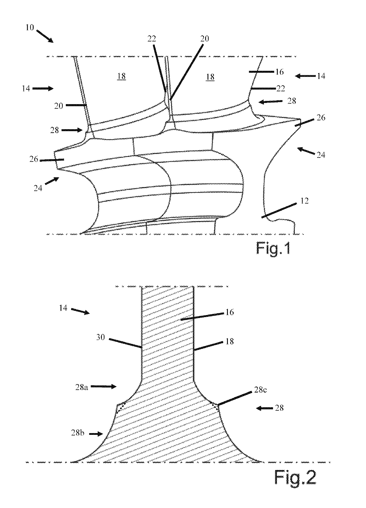
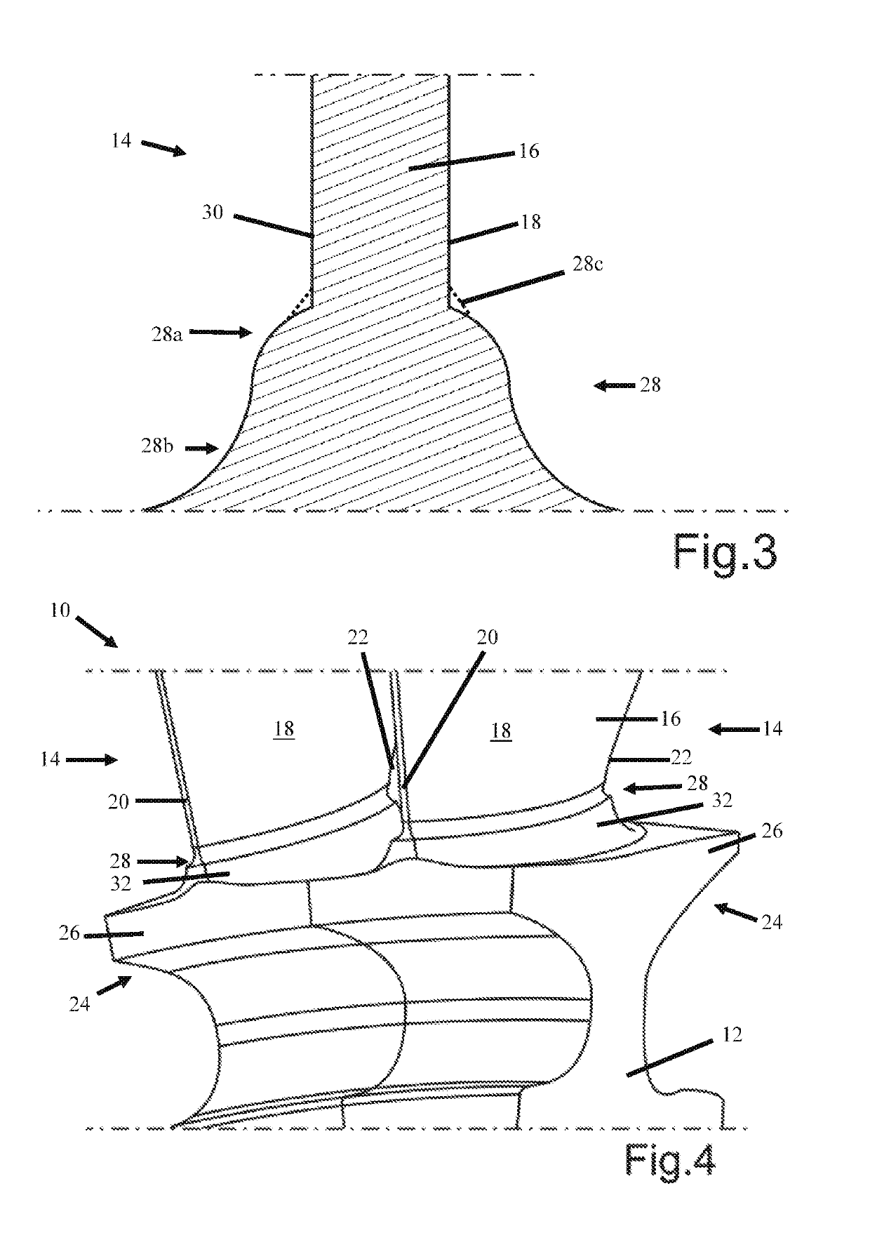
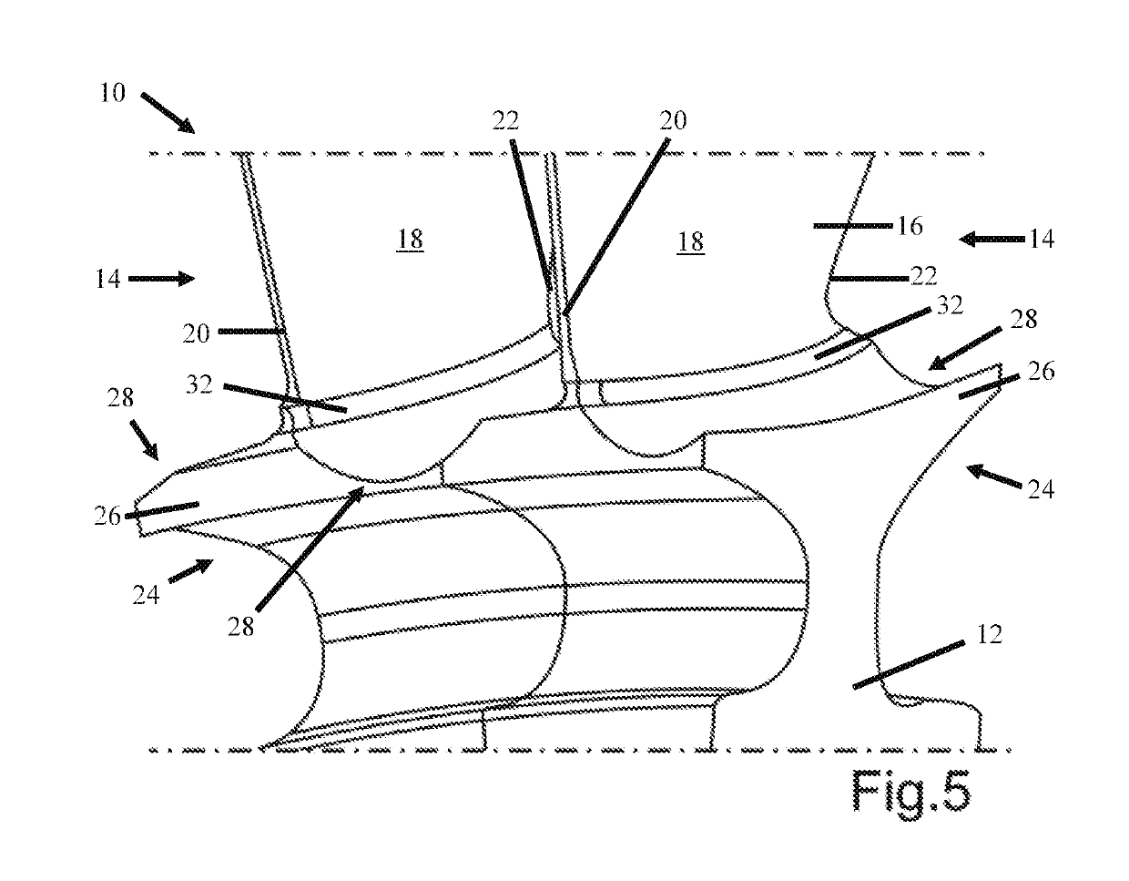
[0063]FIG. 1 shows a schematic and excerpted perspective view of a rotor 10 according to the invention in accordance with a first exemplary embodiment. In the present case, the rotor 10 is designed as a blisk (bladed disk) for an aircraft engine and comprises a disk-shaped main rotor body 12, which is integrally furnished with blades 14. In FIG. 1, by way of example, a rotor segment with two blades 14 is illustrated, with the blades 14 being identical in form in the present case. Two or more blades 14 can fundamentally be different in form and / or can be combined to form a blade cluster. Each blade 14 comprises a blade element 16 with a suction side 18 and an opposite-lying pressure side 30 (see FIG. 2), which extend between a leading edge 20 and a trailing edge 22 of the blade element 16. Furthermore, each blade 14 comprises a blade root 24, by way of which the respective blade 14 is connected to the main rotor body 12. In the exemplary embodiment shown, each blade root 24 of the bl...


PUM

PropertyMeasurementUnit
Fractionaaaaaaaaaa
Fractionaaaaaaaaaa
Fractionaaaaaaaaaa

Abstract

The invention relates to a blade for a turbomachine, comprising a blade element with a suction side and a pressure side, which extend between a leading edge and a trailing edge of the blade element, as well as a blade root for connection of the blade at a main rotor body, wherein the blade comprises a crack-affecting device, which, in the radial direction, has an altered cross-sectional geometry in comparison to an aerodynamically optimized blade profile. The invention further relates to a rotor for a turbomachine having at least one such blade, a turbomachine having at least one such blade, and/or with such a rotor as well as a method for producing a blade.

Description

BACKGROUND OF THE INVENTION[0001]The invention relates to a blade and a rotor for a turbomachine. The invention further relates to a turbomachine having at least one such blade or having at least one such rotor.[0002]Blades in rotating turbomachines are subject to high mechanical loads, which are caused, in particular, by centrifugal forces, vibrations, and thermal gradients. When there is an excessive local load, cracks may occur in the material of the blades and grow into the component under the influence of mechanical and thermal stresses. Particularly in the case of integrally bladed rotors, such as, for example, in the case of blisks (bladed disks) or blings (bladed rings), the blades and the disks or rings are composed of an integral or monolithic component. Furthermore, it needs to be taken into consideration that objects can enter the engine and, when they impinge at the blades, can cause a crack. Particularly owing to the combination of these circumstances, cracks can migra...

Claims


Application Information

Patent Timeline
IPC IPC(8): F01D5/14
CPCF01D5/147F01D5/143F05D2220/32F05D2230/50F05D2240/80F05D2250/71F05D2240/301F05D2240/305F05D2240/306F05D2260/941F05D2230/10F05D2240/24F01D5/141F05D2250/711F05D2250/712F01D5/34Y02T50/60F05D2300/611C23C28/042B32B7/00F05D2230/313
Inventor HORN, WOLFGANGTHEURICH, DANIELBECKER, MARTINSTETTNER, AXELSCHUETTE, WILFRIEDJUNGE, MICHAELHACKENBERG, HANS-PETERHALCOUSSIS, ALEXANDERWOLF, HANNES
Owner MTU AERO ENGINES GMBH
Why Eureka
Try Eureka