Pneumatic multi-valve device and production method

Active Publication Date: 2019-04-25
ETO MAGNETIC GMBH
View PDF0 Cites 0 Cited by
  • Summary
  • Abstract
  • Description
  • Claims
  • Application Information

AI Technical Summary

Benefits of technology

This patent describes a pneumatic multi-valve device that is easy to produce, uses less copper, and manages with a smaller number of components. The device also has a simplified production method. Additionally, the device has a venting collection channel with a trough which is formed in the housing base body. Connection channels, which are formed by the housing base body and connected to the venting bores of the cores for air conduction, lead into the trough. An at least one venting channel, which leads to the venting opening, also leads into the trough. The openings of the connection channels and the at least one venting channel are recessed in the direction of the housing connection side, so that the air-conducting connection is ensured by the housing base body side indent or trough, and a flat housing cover design can be created for space-saving applications. The pneumatic connections of the housing are held in the monolithic housing body by overmolding. To save copper for the coil elements, armature guide tubes can be forgone and the armature elements can be guided directly in a centrical passage opening of a coil carrier, which reduces the distance of the armature elements to the coil elements and saves material transition.

Problems solved by technology

The extensive manufacturing process is perceived to be disadvantageous in the case of the known valve devices.
In particular the extensive, air-tight cover fixation via a plurality of screwing processes and the necessity of providing an elastomeric ring seal is disadvantageous.
It is furthermore perceived to be disadvantageous that the housing cover has to be molded in a trough-like manner, in order to connect the venting bores to each other for air conduction or in order to form the venting collection channel, respectively.
It is a further disadvantage of known multi-valve devices that the housing has to be produced in a two-part overmolding process.
In addition, the required amount of copper for forming the coil elements is relatively high.

Method used


Image

  • Pneumatic multi-valve device and production method
  • Pneumatic multi-valve device and production method
  • Pneumatic multi-valve device and production method

Examples


Embodiment Construction

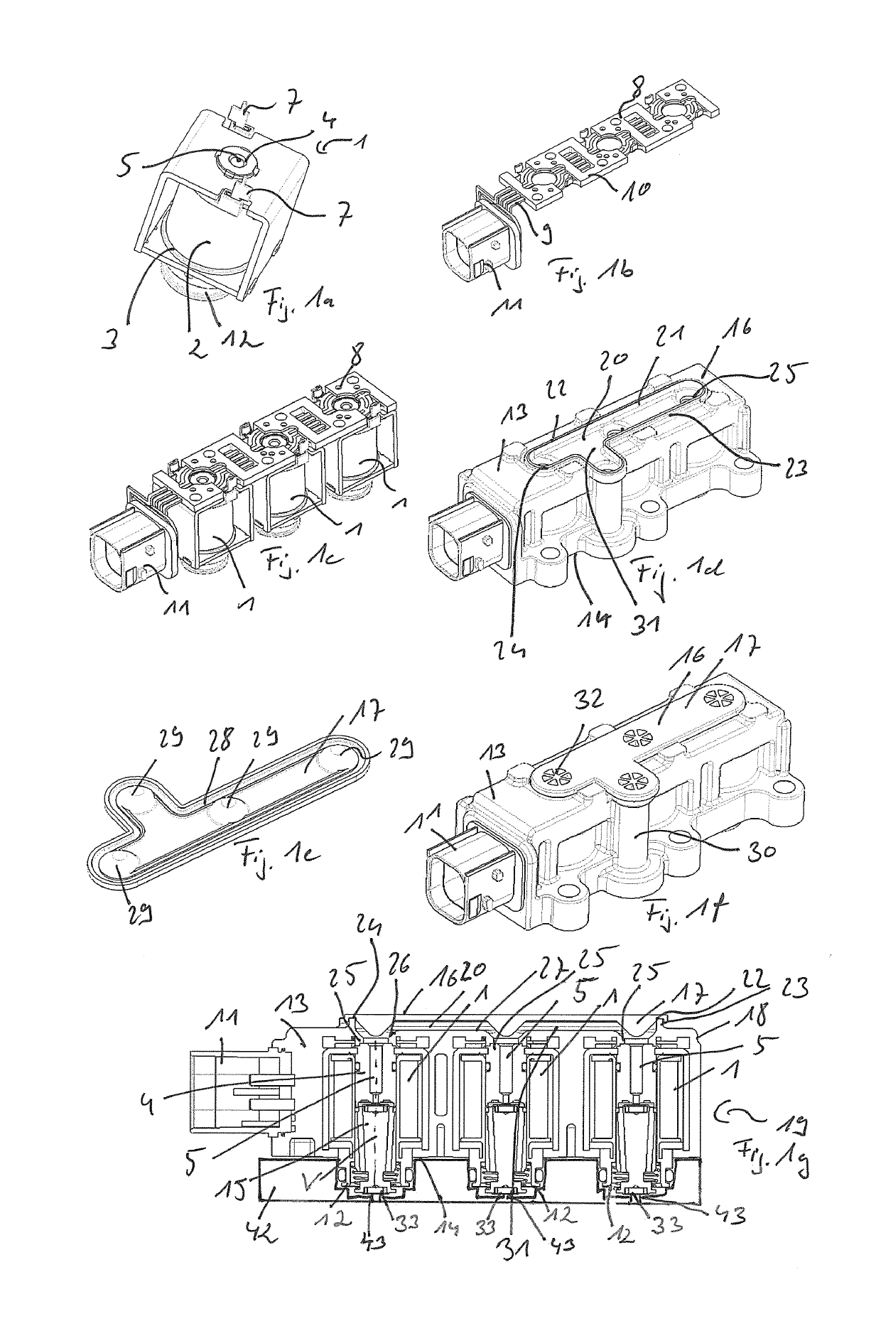
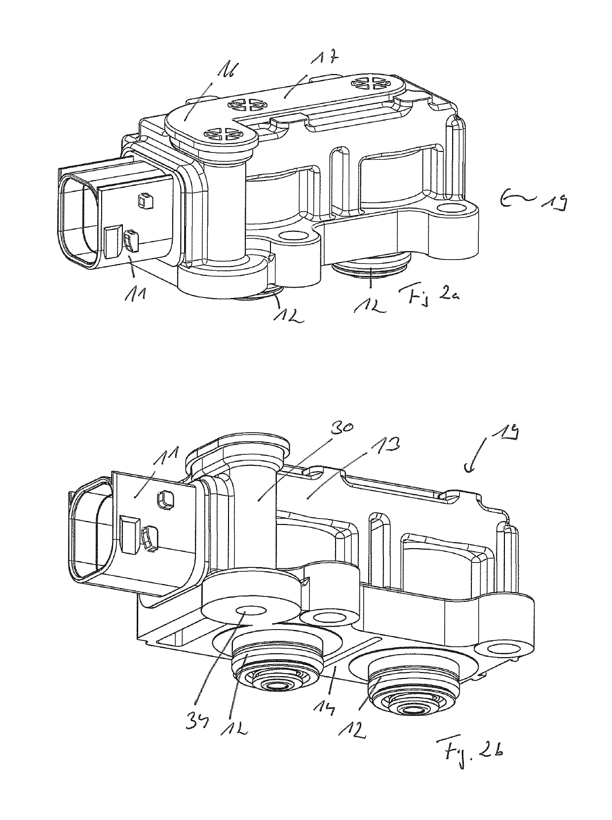
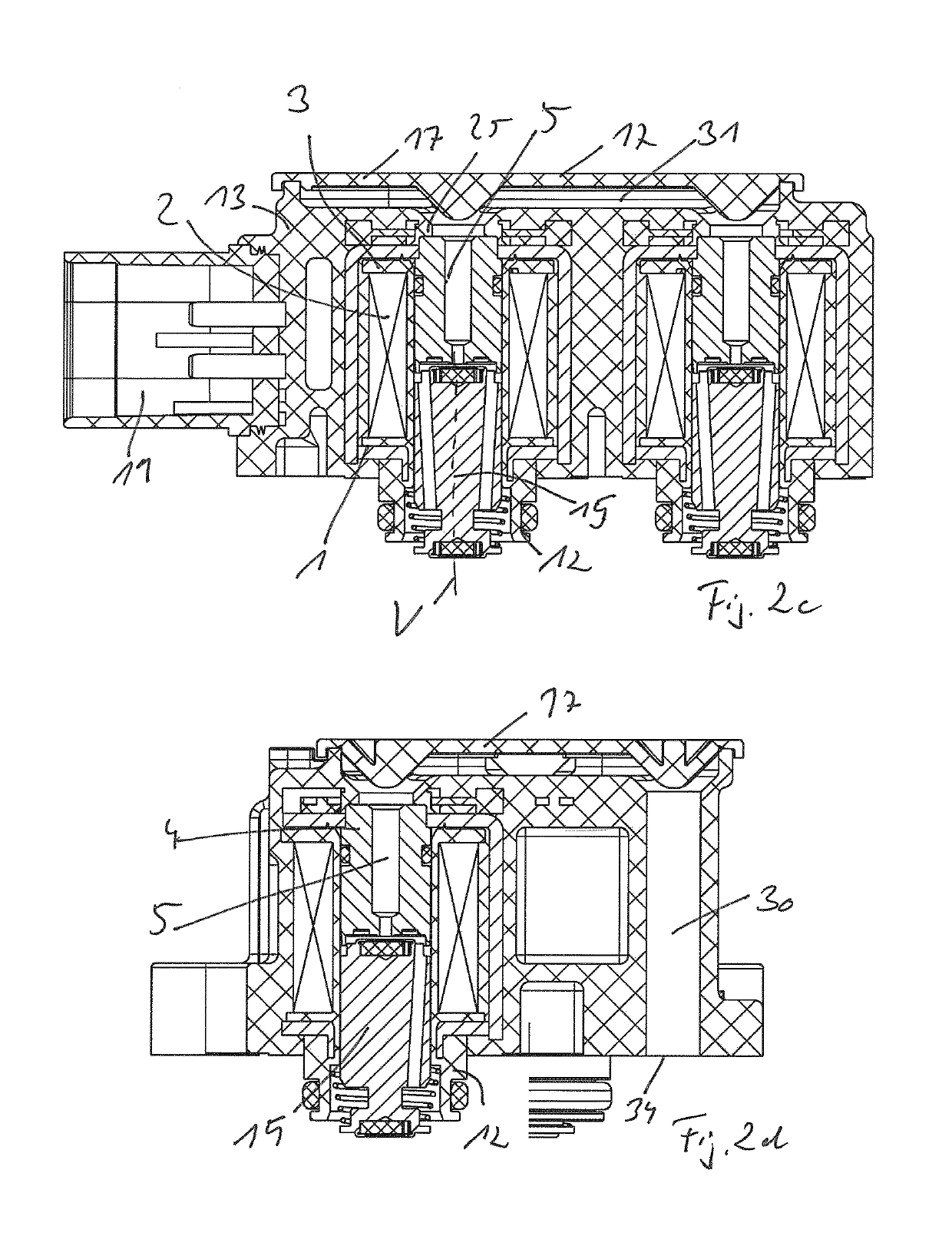
[0030]FIGS. 1a to 1e show different assembly steps and components for producing a valve device according to the invention, which is illustrated in FIG. 1f in a perspective view and which, in turn, is illustrated in a sectional view in FIG. 1g.

[0031]FIG. 1a shows a preassembled, electromagnetic valve actuator 1, of which a plurality—here for example three pieces—is provided in the finished multi-valve device (valve block) illustrated in FIGS. 1f and 1g. The electromagnetic valve actuator 1 comprises an energizable coil element 2 (electrical winding), which is arranged on a coil carrier 3, which is embodied as plastic injection molded part. A core 4 for the electromagnetic interaction with non-illustrated armature elements is located in a central passage opening (central bore) of the coil carrier 3. A central venting bore 5 is provided in the core 4. The coil elements 3 are clasped by a magnetically conducting yoke 6 for surrounding the magnetic circuit. Electrical contact elements 7...


PUM


Abstract

A pneumatic multi-valve device (valve block), including a housing (18), which has a housing main body (13) with a plurality of electromagnetic valve actuators (1), each having coil elements (2) arranged in the housing (18) in a stationary manner, a core (4) arranged in the housing (18), and armature elements (15), which can be displaced along a displacement axis (V) in the housing (18) in relation to the core (4) and in relation to a pneumatic connection (12) of the housing (18) in response to energizing of the coil elements (2), wherein the displacement axes (V) of the armature elements (15) of the valve actuators (1) are oriented parallel and the pneumatic connections (12) associated with the armature elements (15) are arranged adjacent to each other on a connection housing side (14), which is spaced apart from a housing back side (16) facing away therefrom along the displacement axes (V), wherein the cores (4) each have a venting bore (5), which is connected, for air conduction, to a venting collection channel (31) on the side of the cores (4) facing away from the connection housing side (14), which venting collection channel is bounded on the housing back side (16) by a housing cover (17) fastened to the housing main body (13), which venting collection channel is connected, for air conduction, to a venting opening of the housing (18), which venting opening is arranged on a housing side different from the housing back side (16), in particular on the connection housing side (14) having the pneumatic connections (12), wherein the housing cover (17) is fixed to the housing base body (13) via an air-tight welded connection (35), in particular an ultrasonic or laser welded connection.

Description

BACKGROUND OF THE INVENTION[0001]The invention relates to a pneumatic multi-valve device (valve block), in particular for use in electronically regulated air spring systems of vehicles, preferably utility vehicles, comprising a housing, which has a housing main body with a plurality of electromagnetic valve actuators, each having coil elements arranged in the housing in a stationary manner, a core arranged in the housing, and armature elements, which can be displaced along a displacement axis in the housing in relation to the core and in relation to a (respective) pneumatic connection of the housing in response to energization of the coil elements, wherein the displacement axes of the (plurality of) armature elements of the valve actuators are oriented parallel and the pneumatic connections associated with the armature elements are arranged adjacent to each other on a connection housing side, which is spaced apart from a housing back side facing away therefrom along the displacement...

Claims


Application Information

Patent Timeline
IPC IPC(8): F16K27/02F16K27/00
CPCF16K27/029F16K27/003
Inventor BRUCZUK, WITOLDBUNIO, MARIUSZZINSER, MICHAEL
Owner ETO MAGNETIC GMBH
Why Eureka
Try Eureka