Camera module and vehicle

Active Publication Date: 2019-04-25
LG INNOTEK CO LTD
View PDF0 Cites 9 Cited by
  • Summary
  • Abstract
  • Description
  • Claims
  • Application Information

AI Technical Summary

Benefits of technology

The camera module described in this patent is made up of two parts, each made from plastic, that are fused together. The module contains many electronic parts and is designed to reduce electromagnetic interference. The module also includes a connector that allows for easy discharge of residual electromagnetic waves. Additionally, the module has a PCB arranged at a holder to prevent damage and moisture infiltration. The PCB is protected by an optical hardening adhesive to improve adhesive bonding performance. The vehicle-mounted camera module is also provided.

Problems solved by technology

Particularly, vehicles coupled with a camera module have been marketed concomitant with sophistication of vehicular parts and automation.
The metal material is expensive (about 10 times more expensive than plastic), and because a front body and a rear body are screw-connected, a screw groove is required to couple the front body and the rear body.
Hence, there may be generated a problem where a space is limited for installing the electronic parts.
However, disadvantage is that the residual electromagnetic wave in shield can is difficult to be emitted to outside because of external member of non-conductive plastic material.
Thus, the electromagnetic wave accumulated in the shield can may disadvantageously result in occurrences of erroneous operation due to influence affected on the electronic parts by the electromagnetic wave.
When the circuit substrate and the holder are mutually coupled using the optical hardening adhesive, the circuit substrate has a structure of protruding toward an outside of holder, whereby various problems may be generated due to the protruded structure.
The first problem is that an entire volume of camera module may be greatly increased when the circuit substrate is protruded outside of the holder.
The second problem is that the circuit substrate may be easily separated from the holder or damaged by external impact when the circuit substrate is protruded outside of holder.
The third problem is that hermeticity may be deteriorated to allow moisture or foreign object to be easily introduced into the holder when the circuit substrate is protruded outside of holder.
However, when the circuit substrate is disposed at the concave reception part formed at the holder, a sufficient light cannot be provided to the optical hardening adhesive formed between the holder and the reception part to greatly reduce an adhesion performance caused by non-hardening of adhesive, and as a result, there may be generated a problem of the circuit substrate being easily separated from the holder.

Method used


Image

  • Camera module and vehicle
  • Camera module and vehicle
  • Camera module and vehicle

Examples


Embodiment Construction

[Technical Subject]

[0016]Exemplary embodiments of the present invention are to provide a camera module configured to arrange an external member with a plastic material to secure a wide parts accommodation space and to simultaneously implement an electromagnetic stability by being grounded to a shield can as well.

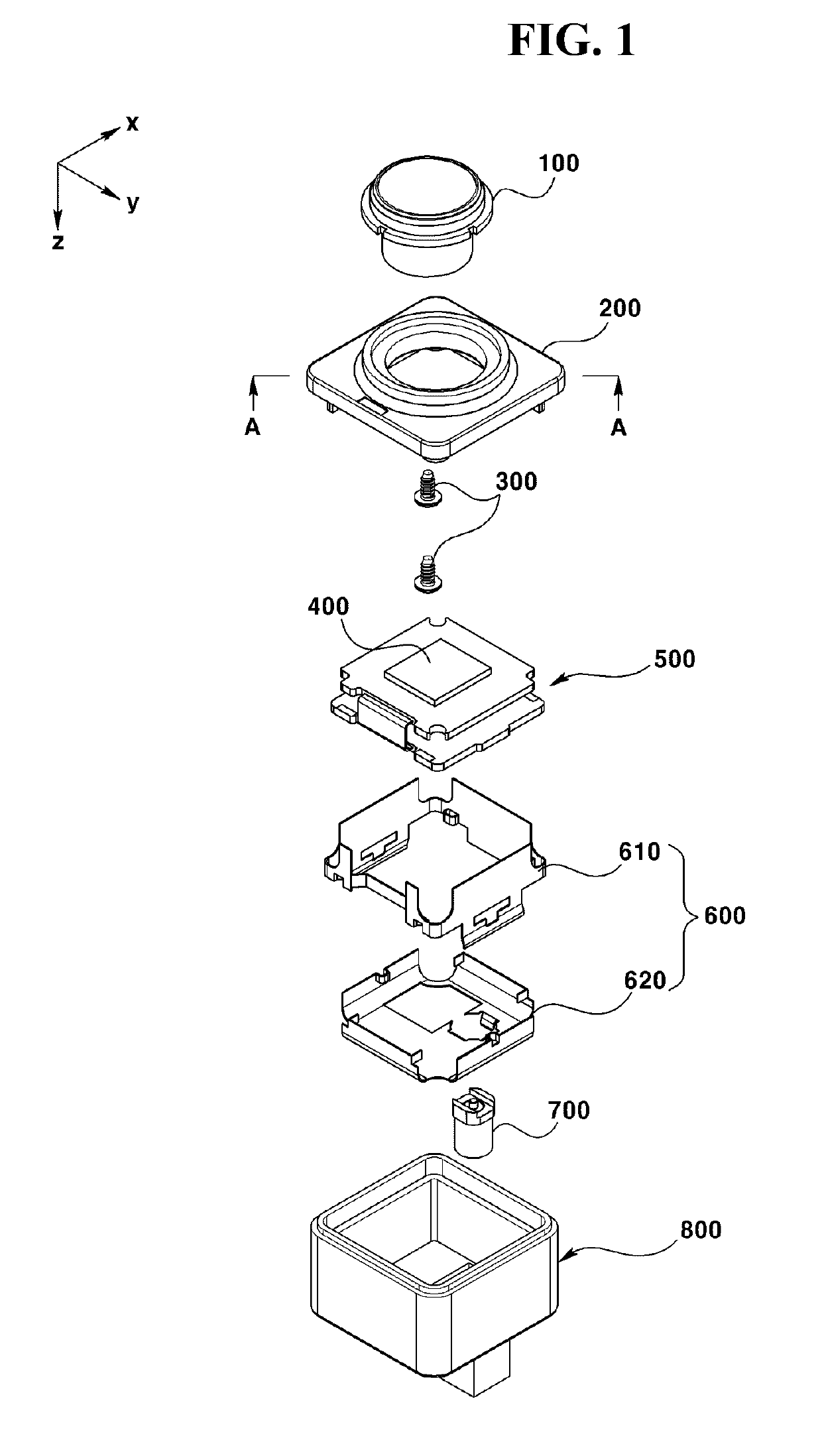
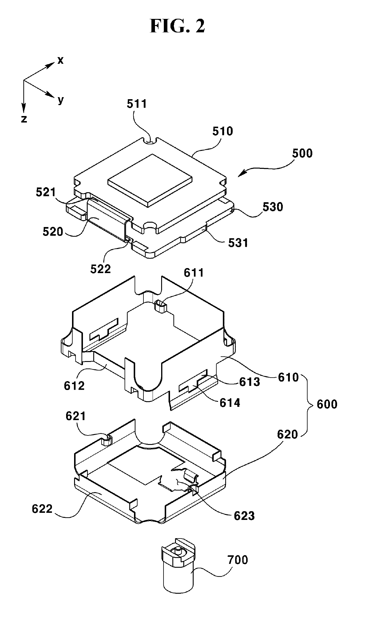
[0017]Exemplary embodiments of the present invention are to provide a camera module configured to respectively prevent the volume increase, separation or damage and moisture infiltration by arranging a PCB mounted with an image sensor in a reception part concavely formed on a holder, and to greatly improve an adhesion performance of optical hardening adhesive by implementing a sufficient hardening by providing a reflected light to an area where a light cannot be reached directly to the optical hardening adhesive because of the PCB being disposed within the reception groove part.

[0018]Furthermore, exemplary embodiments of the present invention are to provide a vehicle mounted...


PUM

PropertyMeasurementUnit
Diameteraaaaaaaaaa
Areaaaaaaaaaaa
Circumferenceaaaaaaaaaa

Abstract

The present embodiment provides a camera module and a vehicle comprising same, the camera module comprising: a lens barrel accommodating at least one lens; a front body accommodating the lens barrel; a substrate assembly which couples with the front body, is disposed so as to be spaced apart from the lens barrel, and comprises at least one substrate so as to have an image sensor and a connector mounted thereon; a shield can which couples with the substrate assembly so as to accommodate at least one portion of the substrate assembly; and a rear body which couples with the front body and accommodates the substrate assembly and the shield can. The shield can comprises: a hole formed in a position corresponding to the connector; and a connection member which is bent and extends towards the inside from the hole. The connector passes through the hole, and the connector has a ground part disposed on the outer surface thereof so that the ground part and the connection member electrically make contact.

Description

TECHNICAL FIELD[0001]The teachings in accordance with exemplary and non-limiting embodiments of this invention relate generally to a camera module and a vehicle.BACKGROUND ART[0002]This section provides background information related to the present invention, which is not necessarily prior art.[0003]A camera module photographing a subject in a photograph or a video may be coupled with various devices and apparatus. Particularly, vehicles coupled with a camera module have been marketed concomitant with sophistication of vehicular parts and automation. The camera modules are used by being embedded in front and rear monitoring cameras and black boxes.[0004]An external member of vehicular camera module is generally formed by allowing a front body mounted with a lens barrel and a rear body accommodated with electronic parts to be coupled, and a metal or plastic is generally used for external member of vehicular camera module.[0005]The metal material is expensive (about 10 times more expe...

Claims


Application Information

Patent Timeline
IPC IPC(8): G02B7/02G02B21/36B29C65/48H04N5/225
CPCG02B7/021G02B21/36B29C65/48H04N5/2254G02B7/02G03B17/02H04N23/00H04N23/55
Inventor PARK, JE KYUNGMOON, DA HINLEE, CHUL HOHWANG, SUN MIN
Owner LG INNOTEK CO LTD
Why Eureka
Try Eureka