Ultrasonic object detection system for motor vehicles and method of operation thereof

a technology of object detection and ultrasonic technology, applied in the direction of scene recognition, anti-theft devices, instruments, etc., can solve the problems of reducing the performance characteristics of the sensor (sensitivity, minimum sensing distance, etc., and the vibrating membrane does not have sufficient time to stabilize, so as to avoid false activation and eliminate feedback and ringing.

Inactive Publication Date: 2019-04-25
MAGNA CLOSURES INC
View PDF0 Cites 10 Cited by
  • Summary
  • Abstract
  • Description
  • Claims
  • Application Information

AI Technical Summary

Benefits of technology

[0041]Because the ultrasonic transducers emit ultrasonic waves or bursts 24, the rear bumper 18 can include a clearance slot 26, illustratively provided on an underside 21 of the rear bumper 18 as best shown in FIGS. 4, 6A-6B, 7A-7C, and 8A-8C, to allow ultrasonic waves (ultrasonic bursts 24 and ultrasonic echoes 25) to be conveyed to and/or from each ultrasonic transducer 20, for example between the rear liftgate 14 and the ground 27 (FIGS. 9, 10, 13, and 14). According to one embodiment, the ultrasonic object detection system 10 includes a single ultrasonic transducer 20, as shown in FIGS. 6A-6B and 8A-8C. According to one embodiment, the ultrasonic object detection system 10 includes a pair of ultrasonic transducers 20A, 20B, referred to as dual sensors, as shown in FIGS. 7A-7C. In this embodiment, one of the ultrasonic transducers 20A, 20B transmits and the other receives or listens, as best shown in FIGS. 9 and 10. The ultrasonic transducers 20A, 20B provide the system 10 with an advantage over comparative systems which only include a single ultrasonic transducer 20. If there is only a single ultrasonic transducer 20, due to close range, feedback and ringing (e.g. a non-stable sensor membrane) which interferes with operation and detection can occur. The dedicated transmit (Tx) and receive (Rx) ultrasonic transducers 20A, 20B eliminate this feedback and ringing problem. The ultrasonic transducers 20, 20A, 20B are oriented towards the ground 27, for example to direct pulses/chirp in a vertical direction or substantially vertical direction emanating in illustratively a cone pattern. The term substantially vertical direction is used herein to refer to a direction that is not horizontal such that a detection zone is located either directly beneath or substantially beneath extending from an area directly beneath is provided e.g. a detection cone projecting from the ultrasonic transducers 20, 20A, 20B at a 45 degree angle from the vertical. Such an orientation ensures the ultrasonic transducers 20, 20A, 20B are able to capture gestures (e.g. gestures of a user's foot) in a predefined location to avoid false activations from motions or gestures (e.g. hand or arm or leg gestures) outside the detection zone which do not correspond to gestures made by a user with the intent to activate the ultrasonic transducers 20, 20A, 20B. For example, the detection zone may be configured for detection directly beneath

Problems solved by technology

One drawback of employing ultrasonic sensors relates to the phenomenon known as “ringing”, which reduces the performance characteristics of the sensor (i.e. sensitivity, and minimum sensing distance).
Due to the speed at which the ultrasonic pulse travels to an object and is reflected back to the sensor membrane, the vibrating membrane does not have sufficient time to stabilize to a point where it can pick-up, or detect, the reflected signal (i.e. be induced to vibrate by the reflected wave).
Placing such sensors on cars, especially sports cars with a low ground clearance will not sufficiently positi

Method used


Image

  • Ultrasonic object detection system for motor vehicles and method of operation thereof
  • Ultrasonic object detection system for motor vehicles and method of operation thereof
  • Ultrasonic object detection system for motor vehicles and method of operation thereof

Examples


Embodiment Construction

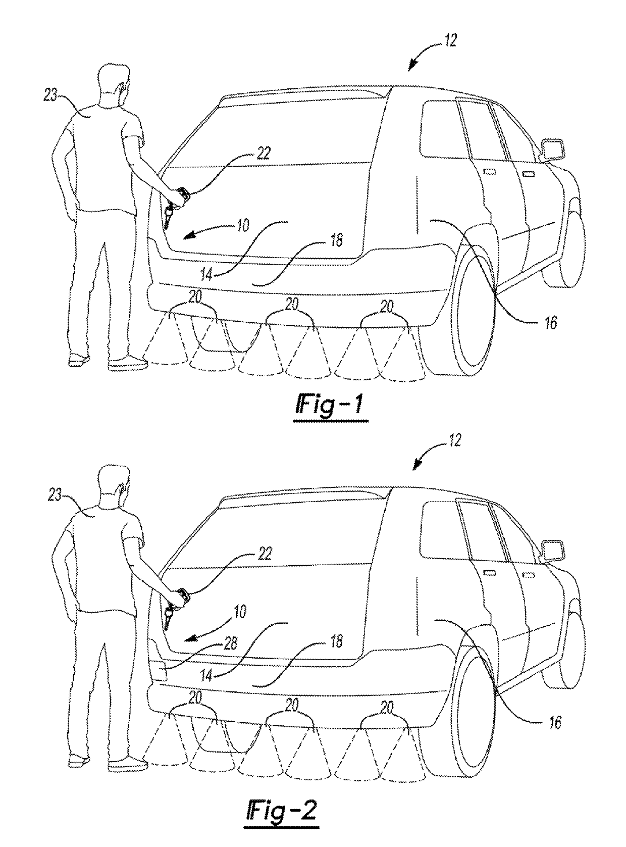
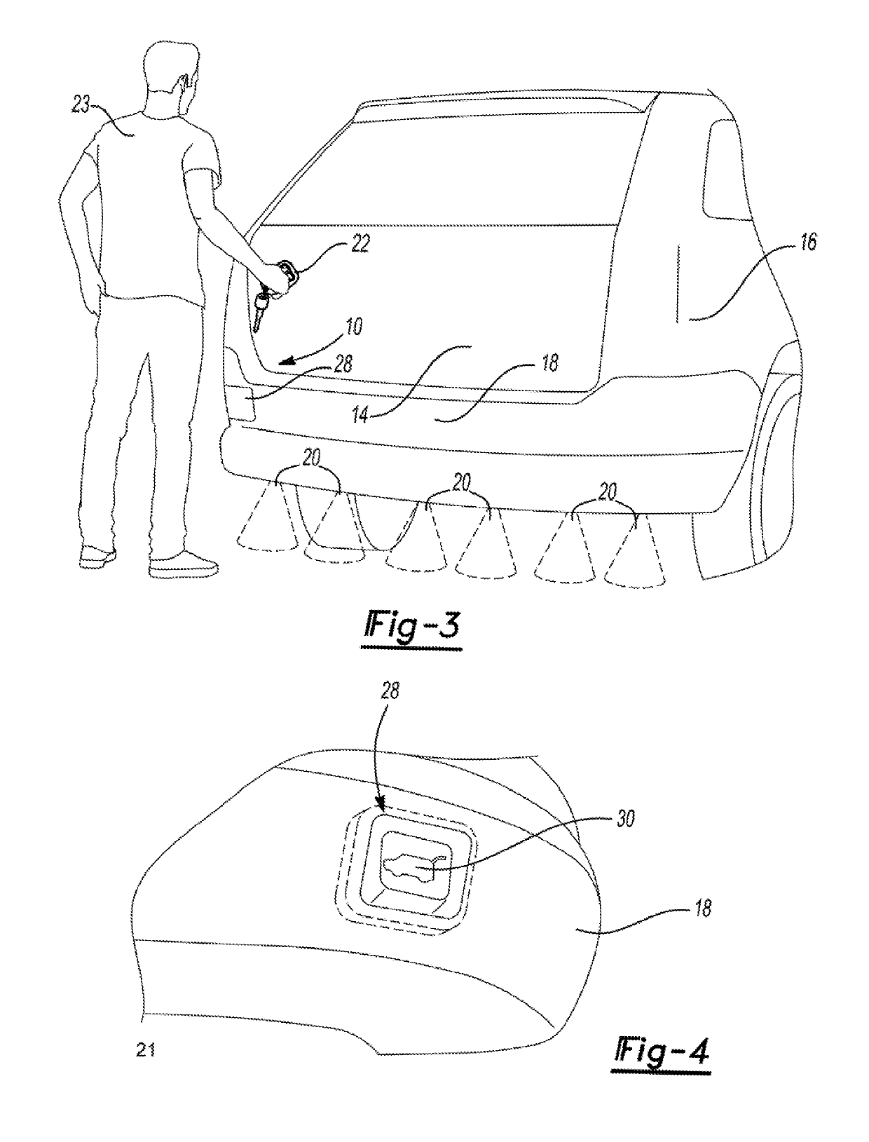
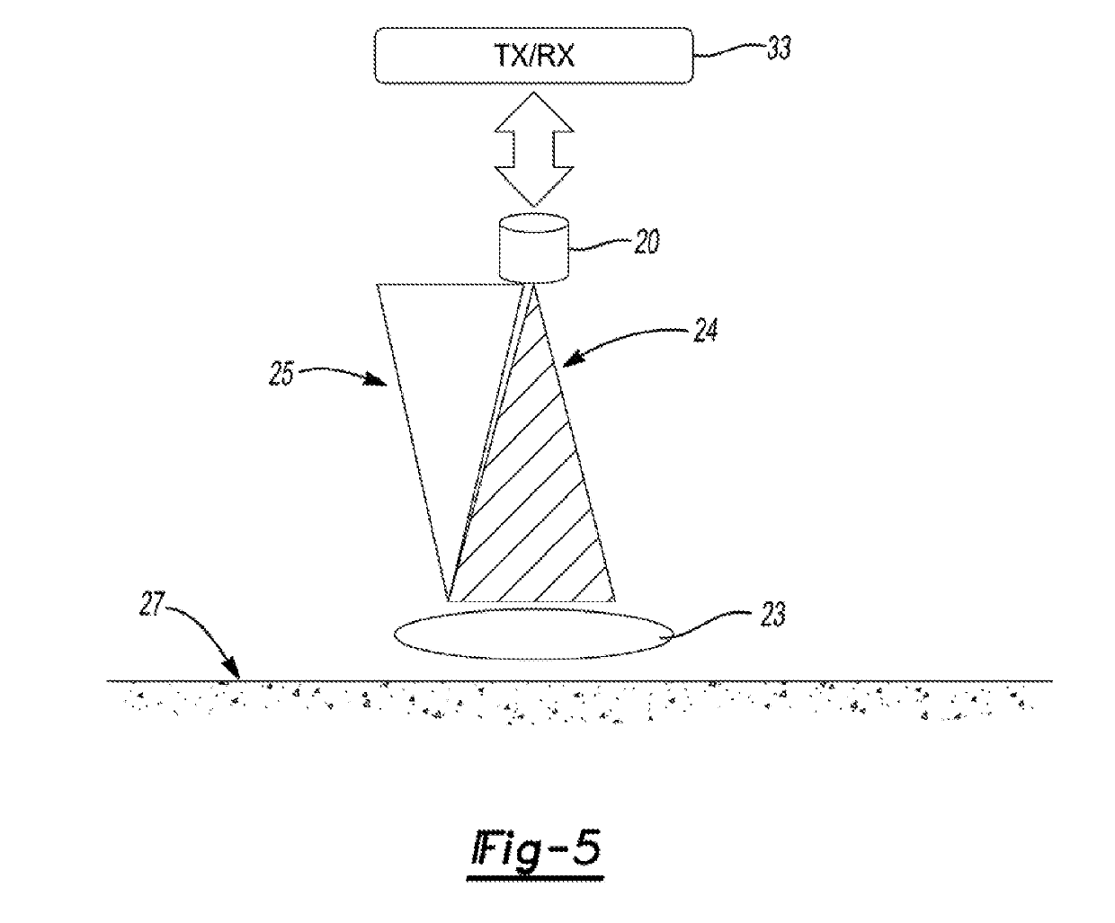
[0038]In general, at least one example embodiment of an ultrasonic object detection system constructed in accordance with the teachings of the present disclosure will now be disclosed. A method of operating the ultrasonic object detection system constructed in accordance with the teachings of the present disclosure will also be disclosed. The example embodiments are provided so that this disclosure will be thorough, and will fully convey the scope to those who are skilled in the art. Numerous specific details are set forth such as examples of specific components, devices, and methods, to provide a thorough understanding of embodiments of the present disclosure. It will be apparent to those skilled in the art that specific details need not be employed, that example embodiments may be embodied in many different forms and that neither should be construed to limit the scope of the disclosure. In some example embodiments, well-known processes, well-known device structures, and well-known...


PUM


Abstract

An ultrasonic object detection system for a motor vehicle is provided. The system includes an indicator attached to a vehicle body for informing a user of an appropriate location to make an activation gesture for initiating opening of a closure member. At least one ultrasonic transducer is attached to the vehicle body. An electronic control unit is electrically coupled to the indicator and includes at least one ultrasonic driver electrically coupled to the at least one ultrasonic transducer. The electronic control unit is in communication with a plurality of vehicle controllers and is configured to receive a plurality of operational signals from the plurality of vehicle controllers, detect the activation gesture made by the user with the at least one ultrasonic transducer, and transmit an activation signal to the plurality of vehicle controllers in response to detecting the activation gesture made by the user for operating the closure member.

Description

CROSS-REFERENCE TO RELATED APPLICATIONS[0001]This utility application claims the benefit of U.S. Provisional Application No. 62 / 576,191 filed Oct. 24, 2017. The entire disclosure of the above application is incorporated herein by reference.FIELD[0002]The present disclosure relates generally to object detection systems for motor vehicles and, more particularly, to an object detection system for user-activation of a power closure member system to move a vehicle closure member relative to a vehicle body between a closed position and an open position.BACKGROUND[0003]This section provides background information related to the present disclosure which is not necessarily prior art.[0004]Motor vehicles, such as sports utility vehicles, can be designed to include a user-activated, non-contact power liftgate system for automatically opening a rear liftgate of the vehicle. The power liftgate system includes a sensor to detect motion of the user desiring to open the rear liftgate, for example a...

Claims


Application Information

Patent Timeline
IPC IPC(8): G06K9/00G01H5/00G01S7/521
CPCG06K9/00805G01H5/00G01S7/521B60J1/18G01S15/06G01S15/931G01S7/527G01S15/003G01S15/04G01S15/87G01S15/88G06V40/20B60R25/01E05F15/73G01S7/523
Inventor TRAN, CUONGCORNER, ALLANBOLBOCIANU, LIVIU
Owner MAGNA CLOSURES INC
Why Eureka
Try Eureka