Cooling structure and housing

Active Publication Date: 2019-05-02
FANUC LTD
View PDF3 Cites 3 Cited by
  • Summary
  • Abstract
  • Description
  • Claims
  • Application Information

AI Technical Summary

Benefits of technology

[0008]According to the present invention, it is possible to efficiently

Problems solved by technology

However, when the housing is disposed under an environment where oil mist exists, if the outside air including the oil mist is tak

Method used


Image

  • Cooling structure and housing
  • Cooling structure and housing
  • Cooling structure and housing

Examples


Example

[0014]A preferred embodiment of a cooling structure and a housing according to the present invention will be described in detail hereinbelow with reference to the accompanying drawings.

[Outline of Controller 12 and Display Device 14]

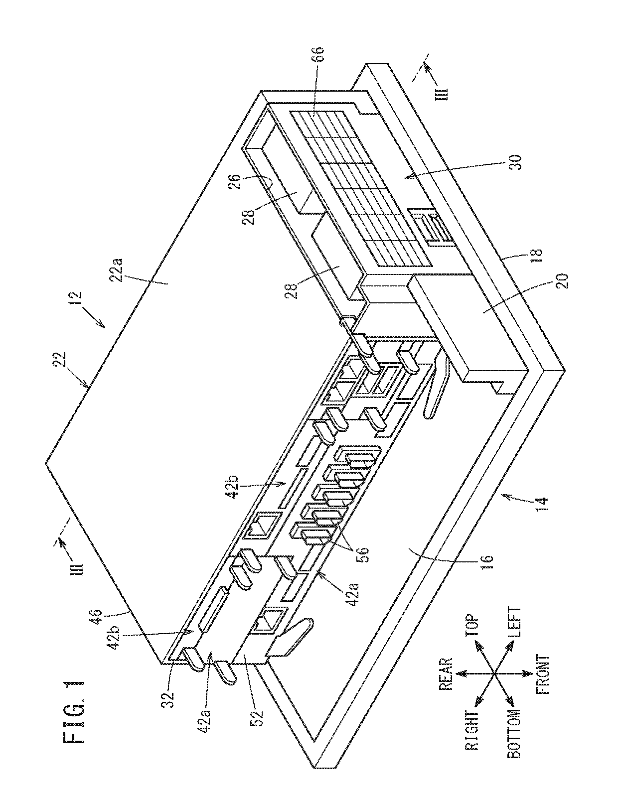
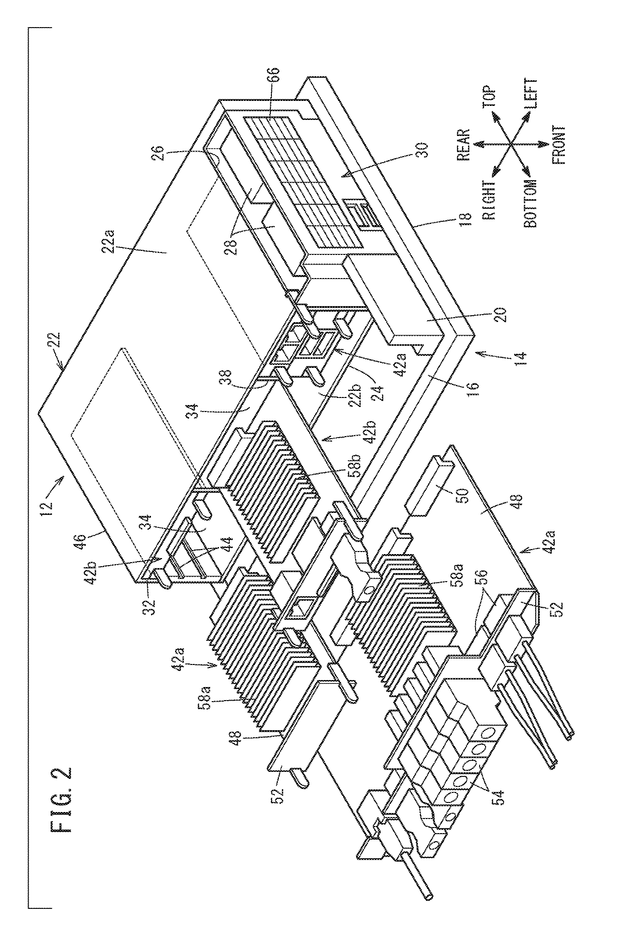
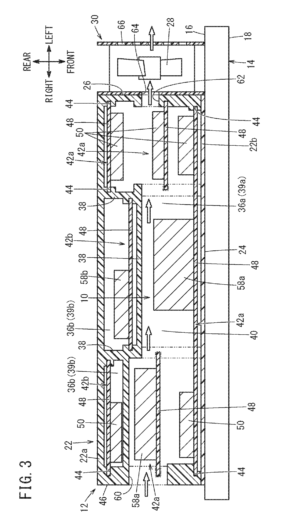
[0015]A cooling structure 10 and a housing 22 of the present embodiment are applied to a controller 12 shown in FIGS. 1 to 3. The controller 12 is arranged on a back face 16 of a display device 14. Here, the configurations of the controller 12 and the display device 14 will be described first, then the cooling structure 10 (see FIG. 3) and the housing 22 (see FIGS. 1 to 3) will be described.

[0016]The controller 12 is a control device for controlling the display device 14. The display device 14 is a liquid crystal display unit having an unillustrated display screen arranged on a front face 18. The controller 12 is applied to, for example, a numerical control device of a CNC (computer numerical control) machine tool. In this case, the display device 14 is ...


PUM


Abstract

A cooling structure includes a housing, a fan for cooling the interior of the housing by generating air flow inside the housing, and a partition provided in the housing to divide the interior of the housing into a first space and a second space. The air flow containing oil mist is taken in from the outside and passed through the first space by driving the fan.

Description

CROSS-REFERENCE TO RELATED APPLICATION[0001]This application is based upon and claims the benefit of priority from Japanese Patent Application No. 2017-210451 filed on Oct. 31, 2017, the contents of which are incorporated herein by reference.BACKGROUND OF THE INVENTIONField of the Invention[0002]The present invention relates to a cooling structure for cooling the interior of a housing by flowing air current in the housing by driving a fan as well as relating the housing in which the interior is cooled by airflow generated by the fan.Description of the Related Art[0003]Japanese Laid-Open Patent Publication No. 2015-138257 discloses a system for cooling a printed circuit board (electronic components) which is disposed behind a display device and is cooled by airflow generated by a fan, in a hermetically sealed (or enclosed) control console.SUMMARY OF THE INVENTION[0004]In order to efficiently cool electronic components disposed in a housing, it is desirable to take in outside air and ...

Claims


Application Information

Patent Timeline
IPC IPC(8): H05K7/20G02F1/1333
CPCH05K7/20972H05K7/20172H05K7/20154G02F1/133385H05K7/20163
Inventor SAIDO, NORIHIRO
Owner FANUC LTD
Why Eureka
Try Eureka