Automatic Matchmaking Device

a matchmaking device and automatic technology, applied in the field of matchmaking, can solve the problem of hard to finish the planing of the common matchmaking device, and achieve the effects of improving the efficiency and practical performance of matchmaking, improving the matchmaking effect, and convenient maintenance and feeding

Inactive Publication Date: 2019-05-09
YU YI
View PDF4 Cites 1 Cited by
  • Summary
  • Abstract
  • Description
  • Claims
  • Application Information

AI Technical Summary

Benefits of technology

[0012]The benefits of the invention are as follows: when the device of this invention is in the initial state, said cutting tool is fully contracted into said third guide chute, and said first guide slider is located on the one end of said fourth guide chute, far away from said cutting cavity, and said second guide slider is located on one tail end of said second guide chute, and said fourth guide slider is located at the top of said first guide chute. At the same time, said fourth guide slider is located on the top of said fifth guide chute, and said third guide slider abuts against said fourth guide slider, and said push rod extends to a maximum extent into said fifth guide chute. At the moment, said arc clamp is in contact with the internal cavity of said cyclic dragging ring, and said slide clamp and said arc clamp are in the same straight line, which is convenient for maintenance and feeding.
[0013]When matchmaking is carried out by using the device of this invention, the round bars to be machined are firstly placed into said cyclic dragging ring, and at the moment said impeller is started to push said fourth guide sliders to move towards each other, and said fourth guide sliders make said arc clamp and said slide clamp tightly clamp the round bars simultaneously; at this moment, one tail end of the round bar extends into said hollow cylinder, and then said motor is started to drive two said rotating shafts to rotate in the same direction to drive said cam, said second gear and said controlling threaded rod to rotate simultaneously. Said cam drives said cutting tool to move periodically into said cutting cavity, and said second gear drives said first gear to rotate to drive said hollow cylinder to rotate. Meanwhile, said controlling threaded rod drives said second guide slider and said cyclic dragging ring as a whole to move to one end, and internally clamped round bars are successively pushed into said cyclic dragging ring, and said shaping tools in said hollow cylinder are started to shape the round bars. As said cyclic dragging ring is moved to one tail end of said material cavity, said cutting tool cuts off the matchsticks with corresponding length, and the formed matchsticks come out of said material returning outlet, which improves the matchmaking effect.
[0014]When the further feeding is needed, said impeller is firstly controlled to contract, and said fourth guide slider, said fifth guide slider and said third guide slider are recovered to the initial position under the action of second pushing spring, which makes said arc clamp and said slide clamp move away from each other and release the round bars, and then said motor is controlled to drive said rotating shaft to rotate reversely, and at this time said rotating shaft still drives said cutting tool and said hollow cylinder to operate, while said rotating shaft drives said controlling threaded rod which rotates reversely to make said second guide slider and said cyclic dragging ring as a whole move to the other end and recover to the initial position. Then said impeller is sequentially controlled to clamp the round bars tightly, and finally said motor is controlled to recover to rotate forward. In conclusion, reciprocating matchmaking may be realized by circulating operations above, which improves the efficiency and practical performance of the matchmaking.
[0015]The device of this invention has a simple structure and is convenient to use as it uses the same power source to realize the automatic and circulating feeding, planing operation and automatic and accurate material cutting, and all the processes are closely coordinated but not to affect their separate operation. Moreover, this device is high in automatic degree, good in matchmaking effect and saves wood, and meanwhile, the practical performance of the device is greatly improved.

Problems solved by technology

However, there always has been a rather difficult technical problem in the technical field of matchmaking, that is, it's hard for common matchmaking devices to finish planing because the diameter of the match is quite small.

Method used


Image

  • Automatic Matchmaking Device

Examples


Embodiment Construction

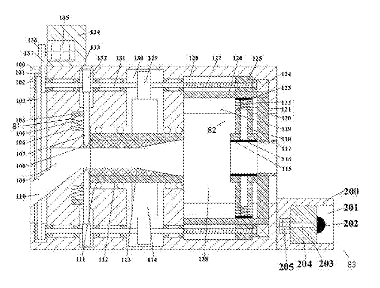
[0018]Referring to FIG. 1, an automatic matchmaking device of this invention comprises a machine body 100, a cylindrical machining cavity 111 arranged in said machine body 100, a material cavity 138 with an opening towards one side communicated with the inner wall of one end of said cylindrical machining cavity 111, first guide chutes 119 which are up and down symmetrical communicated with the upper and lower inner walls of said material cavity 138, wherein the inner walls of said first guide chutes 119, far away from said material cavity 138, are internally communicated with second guide chutes 128; a first cavity 130 which penetrates through said cylindrical machining cavity 111 disposed in said machine body 100, a cutting cavity 109 communicated with the inner wall of the other end of said cylindrical machining cavity 111, a material returning outlet 110 which is tilted downwards communicated with the inner wall of the bottom of said cutting cavity 109, second cavities 133 which ...


PUM

PropertyMeasurementUnit
diameteraaaaaaaaaa
elasticaaaaaaaaaa
timeaaaaaaaaaa

Abstract

This invention discloses an automatic matchmaking device, comprising a machine body, a cylindrical machining cavity arranged in the machine body, a material cavity communicated with the inner wall of one end of the cylindrical machining cavity, first guide chutes communicated with the upper and lower inner walls of the material cavity, wherein the inner walls of the first guide chutes are internally communicated with second guide chutes; a first cavity disposed in the machine body, a cutting cavity communicated with the inner wall of the other end of the cylindrical machining cavity, wherein the cutting tool is periodically driven to move into the cutting cavity through a cam, a material returning outlet communicated with the inner wall of the bottom of the cutting cavity, wherein the cutting tool cuts off the matchsticks with corresponding length, and the formed matchsticks come out of the material returning outlet.

Description

CROSS-REFERENCES TO RELATED APPLICATIONS[0001]The present application claims priority from Chinese application No. 2018103793060 filed on 2018 Apr. 25 which is hereby incorporated by reference in its entirety.TECHNICAL FIELD[0002]The invention relates to the technical field of matchmaking, in particular to an automatic matchmaking device.BACKGROUND OF THE INVENTION[0003]With the development of science and technology and the progress of society, our country always promotes the development of high technology. However, there always has been a rather difficult technical problem in the technical field of matchmaking, that is, it's hard for common matchmaking devices to finish planing because the diameter of the match is quite small. What's more, the process of continuous feeding, planing and cutting may not be synchronously completed, and separate processes are adopted, which affects the effect and efficiency of match processing, while this device solves this problem effectively.BRIEF SU...

Claims


Application Information

Patent Timeline
Patent Type & Authority Applications(United States)
IPC IPC(8): C06F1/02B27L9/00
CPCC06F1/02B27L9/00
Inventor YU, YI
Owner YU YI
Why Eureka
Try Eureka