Tracked vehicle

a track belt and vehicle technology, applied in the field of track belts, can solve the problems of high temperature load on the outer lugs of the track belts, track pads, and high temperature in the outer lugs, and achieve the effect of reducing the number of tracks

Active Publication Date: 2019-05-09
CLAAS INDTECHN
View PDF2 Cites 6 Cited by
  • Summary
  • Abstract
  • Description
  • Claims
  • Application Information

AI Technical Summary

Benefits of technology

[0013]According to one particularly preferred embodiment, the evaluation device is a mobile evaluation device, i.e., an evaluation device which is not necessarily fixedly connected to the vehicle. A mobile evaluation device is, in particular, a smartphone, a tablet computer, a notebook, or the like. One essential advantage in this case is that such an evaluation device can be carried along by any operator, which is common anyway nowadays, in particular, in the case of a smartphone, whereby the evaluation device can also be utilized for different tracked vehicles, in particular, agricultural tracked vehicles.

Problems solved by technology

During road travel, the outer lugs of the track belts or, in the case of rubber belts, the track pads, are subject to a high temperature load because, when they are located under the land rollers, they are repeatedly compressed and unloaded and, due to the hard pavement, cannot escape into the ground.
In the case of high ambient temperatures and a long drive time, the temperature in the outer lugs can increase to such an extent that they “boil up”.
The bead forming as a result then results in a greatly increasing wear of the particular track belt.
In addition, the outer lugs wear comparatively rapidly due to the abrasive pavement.
This disadvantageous effect frequently occurs specifically during transport travel and when there is a high specific load on the track belts, which significantly increases the wear costs for the end customer.
The disadvantage of all these systems, however, is that vehicle-side sensors must be present or scaffolded and, therefore, the system is bound to the vehicle.
Such sensors in the ground engagement elements, for example, in the track belt, mean additional manufacturing costs, however, especially since the production technology for introduction into the rubber material is not simple.
In addition, the sensors are utilized in critical environmental conditions (extreme temperatures, vibrations) which increase the risk of failure.
Moreover, the environmental conditions for a wireless transmission of a sensor signal are not ideal, either.

Method used


Image

  • Tracked vehicle
  • Tracked vehicle
  • Tracked vehicle

Examples


Embodiment Construction

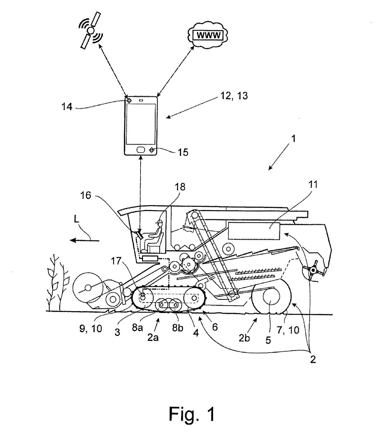
[0028]The tracked vehicle according to the invention, which is designed as an agricultural tracked vehicle 1 in this case, by way of example, can be designed in highly different ways. For example, the agricultural vehicle 1 can be a tractor, self-propelled harvesting machine, such as a combine harvester or a forage harvester, or a driven or non-driven trailer. The benefits of the approach according to the invention are particularly clear in tracked vehicles or half-track vehicles comprising a crawler track assembly. In the exemplary embodiment which is represented and, in this respect, is preferred, the agricultural vehicle 1 is a combine harvester comprising a half-track crawler assembly, as will be explained further below.

[0029]The ground drive 2 of the agricultural vehicle 1 described here by way of example comprises at least two ground drive wheels 3 to 5, which are positioned opposite one another relative to the vehicle longitudinal axis or the direction of travel L. In the vie...


PUM


Abstract

An agricultural tracked vehicle has a ground drive including at least two ground drive wheels. Ground engagement elements are assigned to individual ground drive wheels and/or units comprising several ground drive wheels. An evaluation device is provided, which is configured for ascertaining an operating state of at least one of the ground engagement elements based at least on one or several state variables of the surroundings and/or vehicle-independent, device-specific sensor data.

Description

CROSS-REFERENCE TO RELATED APPLICATIONS[0001]This application claims priority under 35 USC 119 of German Application No. 102017126133.8, filed on Nov. 8, 2017, the disclosure of which is herein incorporated by reference.BACKGROUND OF THE INVENTION[0002]The invention relates to a tracked vehicle, in particular, an agricultural tracked vehicle, and to a method for detecting the operating state and / or determining the service life of at least one ground engagement element of a tracked vehicle.[0003]A tracked vehicle within the scope of the invention is understood to be any form of vehicle comprising a crawler track assembly and, if necessary, an additional wheeled travel mechanism. A tracked vehicle comprises, in particular, a separate ground drive for generating a propulsion, although it can also be a non-driven vehicle, for example, a trailer. Although there is a plurality of different applications which are encompassed by the present invention, the focus in the following is on tracke...

Claims


Application Information

Patent Timeline
Patent Type & Authority Applications(United States)
IPC IPC(8): G07C5/08A01B61/00B62D55/08
CPCG07C5/0808A01B61/00B62D55/08G07C5/0825G07C2205/02G01M17/03G07C5/008B60W40/12B60W2050/146B60K35/00B60W2555/20B60W2556/50B60W2520/10B60W2530/20B60W2552/05B60W2300/15B60K37/06B60K2370/1442B60K2370/176B60K2370/171B60K2370/172B60K2370/1876B60K2370/566B60K2370/573B60K2370/5899B60K2370/592B60W2556/10B60W40/02
Inventor MORAWITZ, MARTINVERHORST, JAN-WILLEMMEYER, PETER
Owner CLAAS INDTECHN
Why Eureka
Try Eureka