
Drug delivery device for liquid pharmaceuticals

a delivery device and liquid pharmaceutical technology, applied in the direction of medical devices, intravenous devices, medical devices, etc., can solve the problems of mechanical instabilities, unpredictable force transmission errors, and jeopardizing dose accuracy, etc., to achieve high mechanical stability, easy assembly, and convenient use

Active Publication Date: 2019-05-16
SIMA PATENT & LISANSLAMA HIZMETLERI LTD STI
View PDF1 Cites 1 Cited by
  • Summary
  • Abstract
  • Description
  • Claims
  • Application Information

AI Technical Summary

Benefits of technology

The present invention aims to provide a drug delivery device that is easy to assemble and use, with high mechanical stability. It requires less force during subcutaneous self-administration and is designed to be user-friendly.

Problems solved by technology

Pen-type injectors on the market usually have multiple snap-on connections in attaching a multi-dose cartridge and a driving mechanism, jeopardizing dose accuracy by mechanical instabilities due to tolerances and loose connections between interrelated parts.
This causes variations in intended volumetric dosages and unpredictable force transmission errors.
High number of snap-on connections increases the risk of unintended disassembly of the device during or after injection.
Furthermore, force required to be exerted onto the device is usually high, which causes inconvenience for those who are physically handicapped or elderly.
Assembly of the individual parts and final assembly of multi-dose cartridge onto the mechanical driving mechanism in such devices are also complicated and not sufficiently reliable.

Method used


Image

  • Drug delivery device for liquid pharmaceuticals
  • Drug delivery device for liquid pharmaceuticals
  • Drug delivery device for liquid pharmaceuticals

Examples


Embodiment Construction

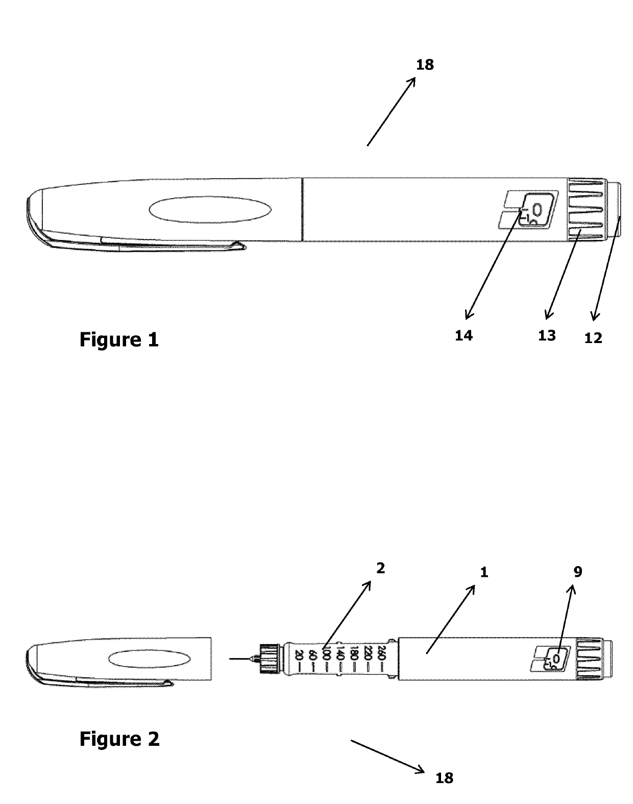
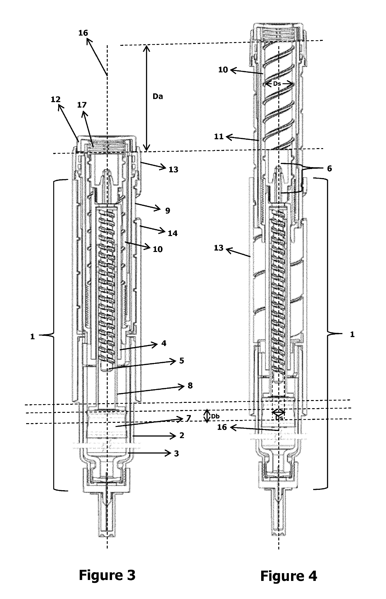
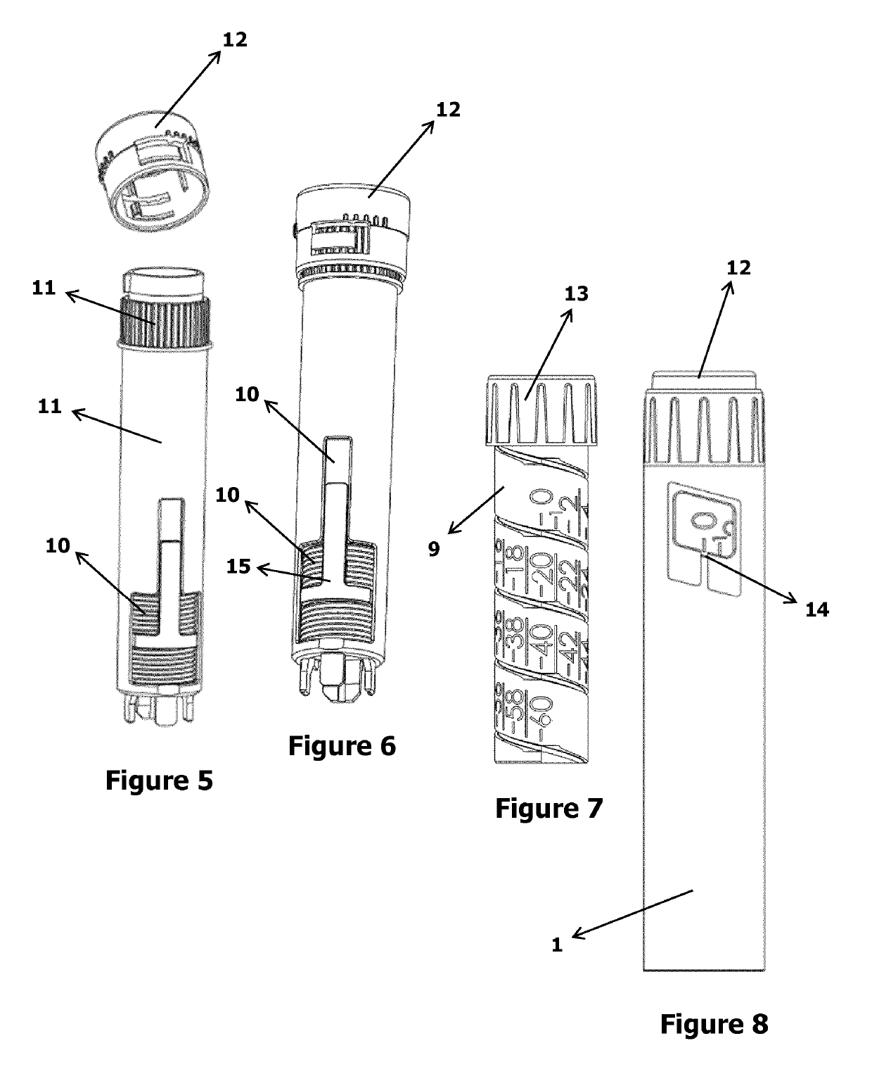
[0028]Referring now the figures outlined above, the present invention proposes a drug delivery device (18) for liquid pharmaceuticals. In other words, the present invention proposes a drive mechanism for multi-dose injectors and a relevant device for multi-dose drug delivery. The device (18) is suitable for use as a medication delivery pen, in particular as a multi-dose insulin delivery pen for use by diabetic patients.

The liquid pharmaceuticals delivery device (18) comprises:

[0029]A mainly cylindrical main body (1), a cartridge (3) having a mainly cylindrical inner cavity with a volumetric capacity for accommodating multiple doses of a liquid pharmaceutical, the cartridge (3) comprising a first end for receiving a plunger (7) and a second end for liquid pharmaceutical extraction; the plunger (7) having a circumferential portion shaped and sized to correspond to the transversal section of the cartridge (3).

The device (18) further comprises:

[0030]A jackscrew (55) comprising a threade...


PUM


Abstract

The present invention proposes a liquid pharmaceuticals delivery device (18) comprising a mainly cylindrical main body (1), a cartridge (3) having a mainly cylindrical inner cavity with a volumetric capacity for accommodating multiple doses of a liquid pharmaceutical, the cartridge (3) comprising a first end for receiving a plunger (7) and a second end for liquid pharmaceutical extraction. The device (18) further comprises a jackscrew (55) a comprising a threaded lower jackscrew (5) and a threaded upper jackscrew (6) integrated or fixed to each other. The jackscrew (55) being rotatable around a primary axis of the main body (1) and stationary along said primary axis, a threaded plunger rod (8) which is integrated to the plunger (7) and which has a thread diameter (Dp) corresponding to thread diameter of the lower jackscrew (5). A button (12) is engageable with the spindle (10), by one thereof having a recess and the other having a protrusion matching said recess along a direction parallel to the primary axis of the spindle (10). The threaded mainly cylindrical spindle (10) has a thread diameter (Ds) corresponding to thread diameter of the upper jackscrew (6). The thread diameter (Ds) of the spindle (10) is greater than the thread diameter (Dp) of the plunger rod (8).

Description

TECHNICAL FIELD OF THE INVENTION[0001]The present invention relates to a drug delivery device for subcutaneous administration of liquid pharmaceuticals.BACKGROUND OF THE INVENTION[0002]Pen-type injectors are widely used by patients applying regular injection without necessitation of formal medical training. Commonly, diabetic patients use such devices for effectively managing their personal treatment.[0003]Pen-type injectors on the market usually have multiple snap-on connections in attaching a multi-dose cartridge and a driving mechanism, jeopardizing dose accuracy by mechanical instabilities due to tolerances and loose connections between interrelated parts. This causes variations in intended volumetric dosages and unpredictable force transmission errors.[0004]High number of snap-on connections increases the risk of unintended disassembly of the device during or after injection. Furthermore, force required to be exerted onto the device is usually high, which causes inconvenience f...

Claims


Application Information

Patent Timeline
Patent Type & Authority Applications(United States)
IPC IPC(8): A61M5/315
CPCA61M5/31551A61M5/31585A61M2005/3126A61M2205/581A61M2205/582A61M5/31575A61M5/31541
Inventor BILGIC, MAHMUT
Owner SIMA PATENT & LISANSLAMA HIZMETLERI LTD STI
Learn More