Unlock instant, AI-driven research and patent intelligence for your innovation.

Hidden image security device and method

Inactive Publication Date: 2019-05-16
CCL SECURE PTY LTD
View PDF5 Cites 0 Cited by
  • Summary
  • Abstract
  • Description
  • Claims
  • Application Information

AI Technical Summary

Benefits of technology

This patent describes an optical device made with a layer of liquid crystal polymer (LCP) that has different heights. The LCP layer includes a grating profile on its outer surface that creates a diffractive effect. This technology allows for the formation of a non-planar surface onto which the liquid crystal layer is applied, which is beneficial for creating secure documents or tokens.

Problems solved by technology

This problem is exacerbated by the fact that the authentication process for the banknote by members of the public has long been recognised as if any, time authenticating their banknotes, which makes it easier for simulations to pass through.
Therefore, although it is difficult to reproduce the optical effect of an optical security element, it is easily possible to create a passable forgery that may appear, without proper inspection, similar to the optical effect.
Forming a liquid crystal layer onto a non-planar surface is relatively difficult for at least two reasons.
First, it can be difficult to create a non-planar surface comprising a relief structure with sufficient difference in height in order to create different optical effects.

Method used


Image

  • Hidden image security device and method
  • Hidden image security device and method
  • Hidden image security device and method

Examples


Embodiment Construction

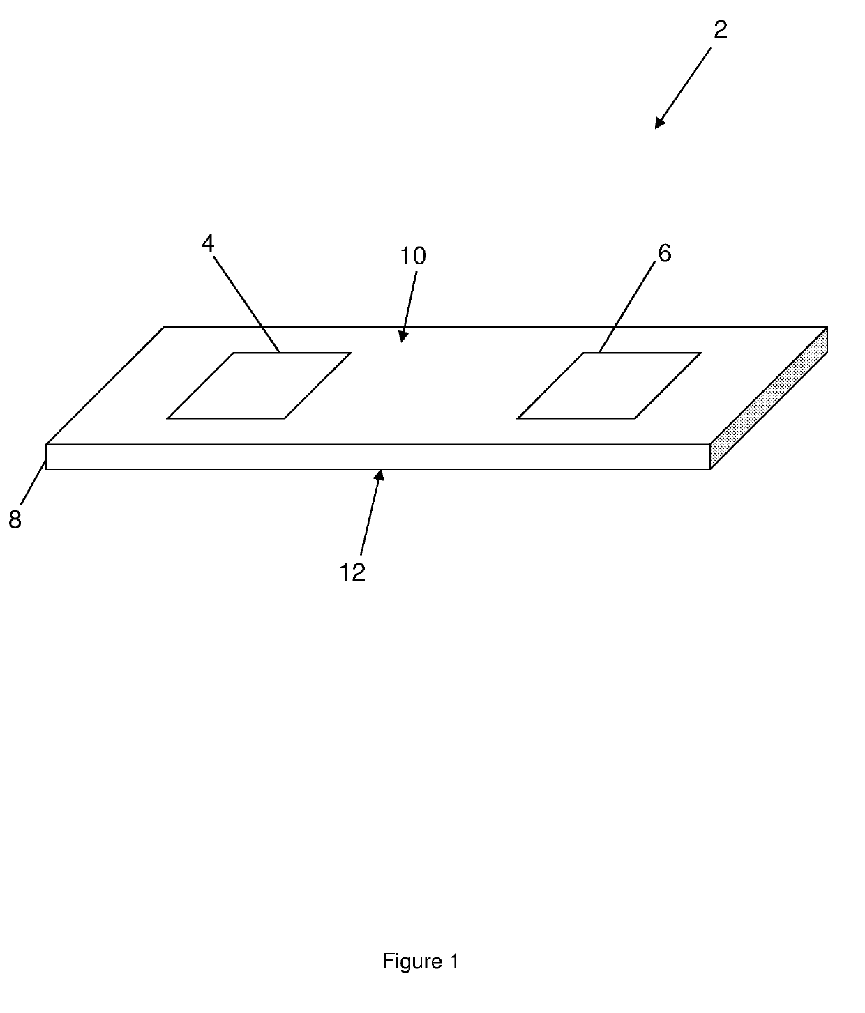
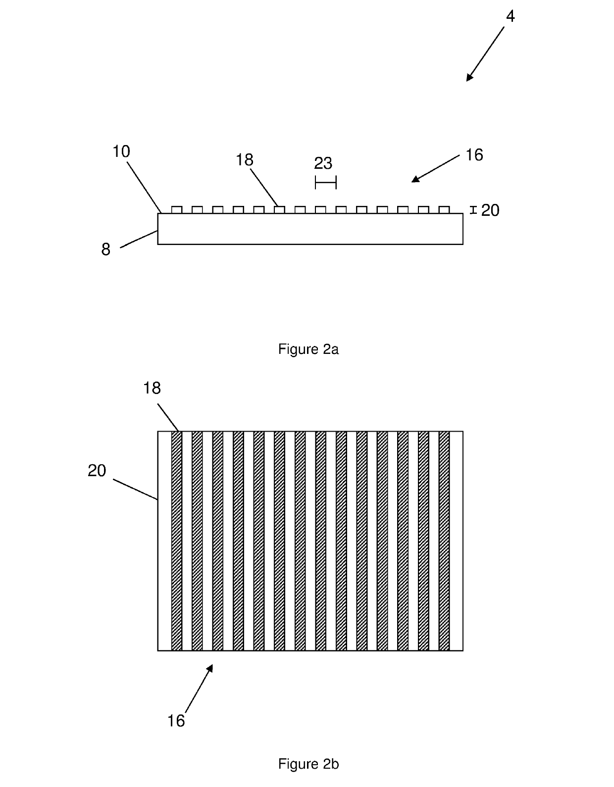
[0074]For the purposes of the following discussion, the figures are to be considered illustrative and not to scale, unless otherwise indicated. The figures illustrate simplified depictions of the embodiments described.

[0075]A “polarising filter” as used herein can be selected from: structural polarisers as described in AU 2011100315; liquid crystal polarisers as described in AU 2012100299; or any other suitable polariser. An “integral polariser” is a polariser formed as part of a security device, for example as formed on a side of a security device.

[0076]“Incident light” is light from a light source incident onto a side of the substrate, and is in general considered to be non-polarised white light (for example, as sourced from an incandescent or fluorescent light source), unless otherwise stated.

[0077]A “visual effect” is an image, pattern, or other visually identifiable effect. A visual effect can be a hidden visual effect, which is only visible under certain conditions, or an over...


PUM


Abstract

A method for producing an optical device, preferably a security device, including the steps of: forming a planar relief structure on a substantially planar first surface of a substrate, preferably a transparent substrate, the planar relief structure having a first alignment direction and including a plurality of relief structure elements each having the same height; and applying a liquid crystal polymer (LCP) layer onto the planar relief structure such that the LCP layer is aligned with the relief structure, wherein the LCP layer includes at least one or more first LCP regions having a first height and one or more second LCP regions having a second height above the substantially planar first surface of the substrate, wherein the second height is different to the first height, and an optical device formed by such a method.

Description

CROSS-REFERENCE TO RELATED APPLICATIONS[0001]The present application is the U.S. national stage application of International Application PCT / AU2016 / 050138, filed Mar. 3, 2016, which international application was published on Sep. 15, 2016, as International Publication WO2016 / 141420. The International Application claims priority of Australian Patent Application No. 2015100280, filed Mar. 6, 2015, and Australian Patent Application No. 2015900803, filed Mar. 6, 2015, the contents of which are incorporated herein by reference in their entireties.FIELD OF THE INVENTION[0002]The invention relates generally to the field of optical security devices, for example as used on banknotes.BACKGROUND TO THE INVENTION[0003]It is well known that many of the world's banknotes, as well as other security documents, carry optical devices which act as security elements. Some optical security elements produce optical effects that vary depending on whether the optical security elements are viewed through a ...

Claims


Application Information

Patent Timeline
IPC IPC(8): B42D25/328B42D25/364B42D25/29B42D25/41
CPCB42D25/328B42D25/364B42D25/29B42D25/41B41M3/003B41M3/14B42D25/324B42D25/351B42D25/425B42D25/45G02B5/1842G02B5/3016G07D7/12
Inventor POWER, GARY FAIRLESSLOK, PHEI
Owner CCL SECURE PTY LTD