Damping Valve, In Particular For A Vibration Damper

Active Publication Date: 2019-05-16
ZF FRIEDRICHSHAFEN AG
1 Cites 0 Cited by

AI-Extracted Technical Summary

Problems solved by technology

The immediate closing of the valve disk causes knocking noises which are objectionable.
The additional star-shaped spring element or spring body complicates the arrangement of flow paths because the ends of the spring connect radially to ...

Method used

[0042]FIG. 6 shows an embodiment based on FIG. 5. Differing from FIG. 5, the elastomeric body 37 is constructed as a tubular body which also forms the throughflow orifice 17. This variant can be introduced very easily in an already existing damping valve body 15 without undertaking changes to the damping valve body. In this case too, proceeding from the annular groove 27, the elastomeric body 37 is somewhat higher than the control edges 29; 31. However, an end face 41 of the elastomeric body 37 facing in direction of the v...

Benefits of technology

[0017]The damping valve body preferably has receiving openings for the at least one elastomeric body. Accordingly, a very simple snap-in connection can easily be realized between the elastomeric body and the damping valve body.
[0018]When the damping valve b...

Abstract

A damping valve includes a damping valve body having at least one throughflow orifice which is at least partially covered by at least one valve disk by the action of a closing force. At least one spring body exerts an opening force on the valve disk that is less than the closing force. The at least one spring body is constructed as an elastomeric body separately from the control edge.

Application Domain

SpringsSprings/dampers design characteristics +4

Technology Topic

EngineeringMechanical engineering

Image

  • Damping Valve, In Particular For A Vibration Damper
  • Damping Valve, In Particular For A Vibration Damper
  • Damping Valve, In Particular For A Vibration Damper

Examples

  • Experimental program(1)

Example

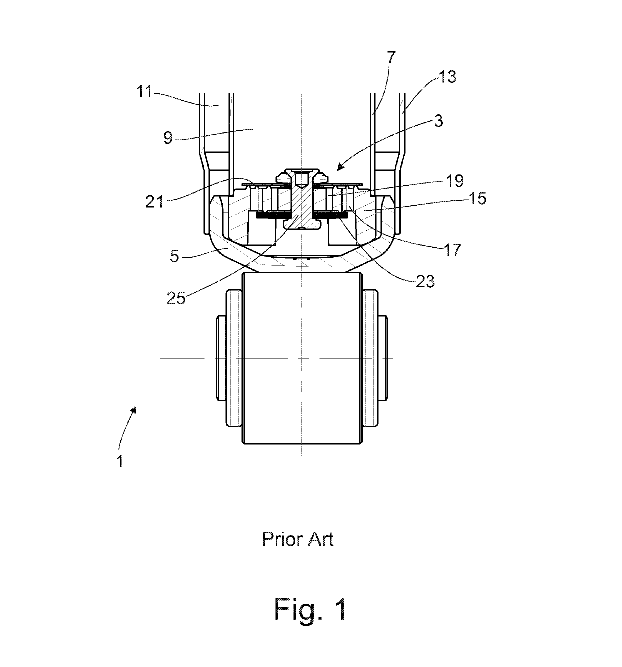
[0036]FIG. 1 shows a section of a vibration damper 1 in the area of a damping valve 3 which is operatively arranged between a working chamber 9 and a compensation space 11 at a base 5 of a cylinder 7. The compensation space is limited by an outer receptacle 13. In principle, the damping valve could also be placed at a piston rod or at any other location.
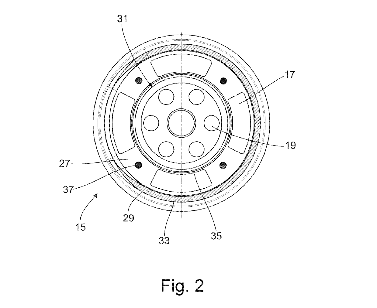
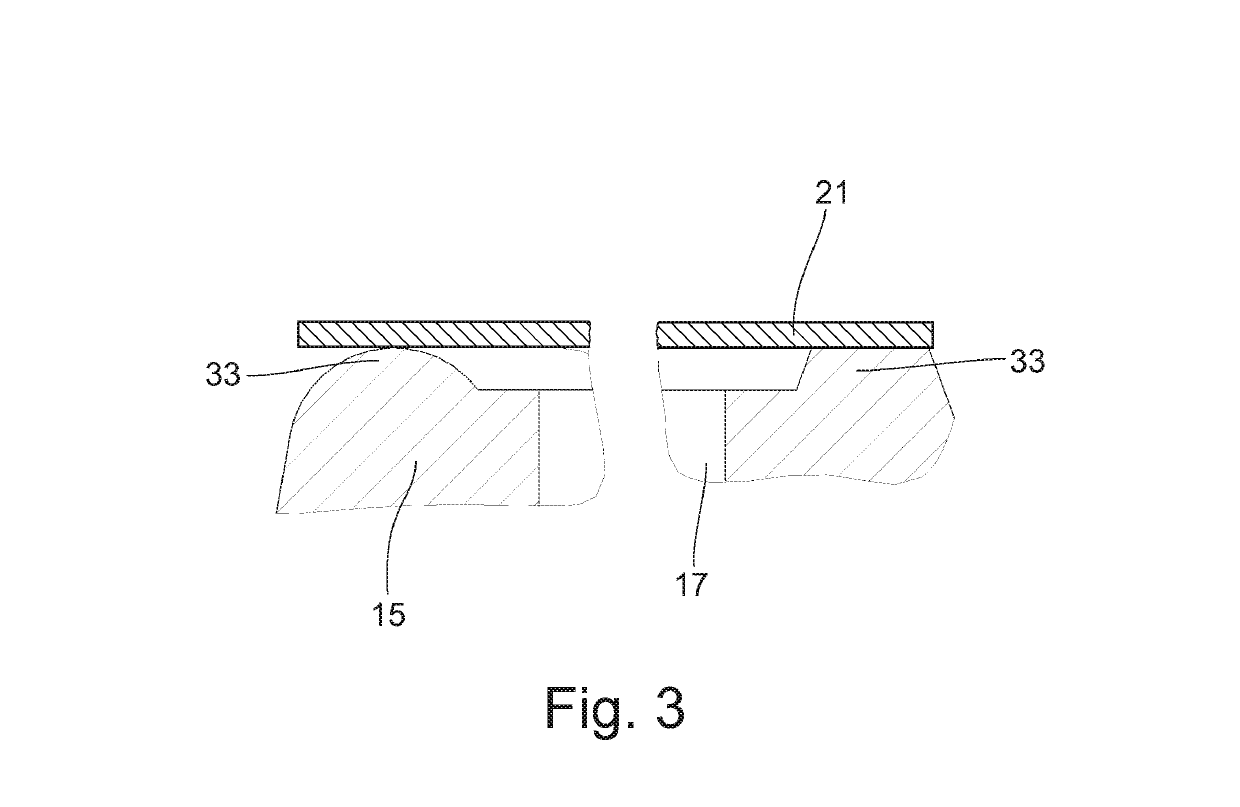
[0037]The damping valve 3 comprises a damping valve body 15 with at least one throughflow orifice 17; 19 which is at least partially covered by at least one valve disk 21; 23 under the action of a closing force. The closing force can be achieved by a spring of any type of construction or by a preloading of the valve disk 17; 19. In the present embodiment, the valve disk is preloaded via a fastening element 25 acting centrally on a valve seat surface.
[0038]As can be further appreciated from FIG. 1, the damping valve 3 has two throughflow directions with separate throughflow orifices on different pitch circles. The throughflow orifices 19 on the smaller pitch circle diameter with valve disks 23 at the underside of the damping valve body 15 provide for the flow through the damping valve proceeding from working chamber 9 into compensation space 11. Throughflow orifices 17 on the outer pitch circle and on the at least one valve disk 21 on the upper side of the damping valve provide for a return flow from compensation space 11 into working chamber 9.
[0039]FIG. 2 shows a top view of the damping valve body 15 viewed from the direction of the working chamber 9. Throughflow orifices 17; 19 for the two throughflow directions are arranged in each instance in an annular groove 27 which is limited by an outer control edge 29 and an inner control edge 31. The control edges define valve seat surfaces 33; 35 for the at least one valve disk 21. In FIG. 2, the throughflow orifices 17; 19 for the two throughflow directions are constructed differently. The cross section of the throughflow orifices is of secondary importance for the present invention. When FIGS. 2 and 3 are viewed together, it will be seen that the outer valve seat surface 33 is crescent-shaped. The crescent shape is achieved through the varying contour of the control edge. The control edge has a curved cross section in the half section on the left-hand side and a trapezoidal cross section in the half section on the right-hand side. Further, the spacing of the two control edges and valve seat surfaces, respectively, can change along the circumference. At the point of greatest distance between the two control edges, the hydraulic center of pressure on the underside of the valve disk 21 is also operative radially at the greatest distance from the valve disk center such that the valve disk 21 first lifts against the closing force when under hydraulic opening force in the area at constant pressure in the annular groove 27.
[0040]FIG. 2 further shows a quantity of spring bodies, here elastomeric bodies 37 between the throughflow orifices and inside the annular groove 27, which elastomeric bodies 37 are formed at a distance from and therefore separately from the control edges 29; 31. FIG. 4 shows a cross section through the damping valve body 15 in the area of an elastomeric body 37 which is formed, e.g., in a barrel-shaped manner with a curved end face. The elastomeric bodies are preferably formed as balls because there is then no preferred installation position. The elastomeric body extends slightly above the level of the control edges 29; 31 and therefore exerts an opening force on the valve disk 21. A blind hole opening 39 for receiving the elastomeric body 37 is provided in the drawing. However, a direct vulcanized joint without an opening can also be provided.
[0041]Referring to FIG. 5, the elastomeric body 37 can also be arranged asymmetrically in order to achieve a purposely one-sided opening force comparable to the function of the crescent-shaped valve seat surface 33. A comparable result can be achieved when the elastomeric bodies 37 have a variable opening force, for example, because of a different cross section, material selection or spring rate.
[0042]FIG. 6 shows an embodiment based on FIG. 5. Differing from FIG. 5, the elastomeric body 37 is constructed as a tubular body which also forms the throughflow orifice 17. This variant can be introduced very easily in an already existing damping valve body 15 without undertaking changes to the damping valve body. In this case too, proceeding from the annular groove 27, the elastomeric body 37 is somewhat higher than the control edges 29; 31. However, an end face 41 of the elastomeric body 37 facing in direction of the valve disk 21 does not form a control edge because the elastomeric body 37 has a lateral opening which leads into the annular groove 27 and, consequently, just a ridge geometry contacts the valve disk.
[0043]FIG. 7 shows a variant in which a plurality of elastomeric bodies 37 which are adjacent in circumferential direction are connected to one another via an elastomeric ring 45. The elastomeric ring 45 can extend over the entire circumference of the annular groove 27 but can also be limited to an angular segment. Additionally, the elastomeric ring 45 can also take over the function of a pre-choke when there are corresponding pre-choke orifices 47 which reduce the cross section of the throughflow orifices 17 in order, for example, to achieve a determined throughflow characteristic with a standardized damping valve body 15.
[0044]In the construction shown in FIG. 8, the pre-choke orifices 47 can be formed in a metallic ring 49 which also carries the elastomeric bodies 37. This variant can support particularly high loading and can be adapted particularly easily owing to the fact that the ring 47 and damping valve body 15 are constructed separately.
[0045]When a flow impinges on the valve disk 21 via the throughflow orifices 17, the entire annular groove 27 fills with damping medium. Accordingly, a hydraulic opening force acts on the valve disk 27. Starting from a closed damping valve position, the elastomeric bodies 37 exert their maximum mechanical opening force on the valve disk 21. If the opening force exceeds the closing force, the valve disk 21 lifts up from its valve seat surface 33. If the closing force on the valve disk 21 is greater than both opening forces, the valve disk 21 again occupies its closed position, and the closing movement of the valve disk is cushioned by the elastomeric bodies 37 until the valve disk 21 is seated again on the valve seat surface 33. An identical behavior would also be possible and useful for valve disk 23 in connection with the throughflow orifices 19.
[0046]Referring to FIG. 9, the elastomeric body 37 can also be arranged on different pitch circles 51; 53. For example, the elastomeric bodies are connected to ring 45. However, an arrangement such as that shown in FIG. 2, for example, i.e., directly in the damping valve body, can also be provided. There is also the option that the elastomeric bodies form an oblique plane with reference to the valve seat surfaces 33; 35 so that, e.g., the elastomeric body on the larger pitch circle 53 projects out axially farther over the valve seat surface 33 than the elastomeric body 37 on the smaller pitch circle 51. In some cases it may also be useful for the elastomeric bodies on the larger pitch circle to have a lesser axial projection, e.g., if the valve disk should preferably lift primarily at the inner diameter.
[0047]Thus, while there have shown and described and pointed out fundamental novel features of the invention as applied to a preferred embodiment thereof, it will be understood that various omissions and substitutions and changes in the form and details of the devices illustrated, and in their operation, may be made by those skilled in the art without departing from the spirit of the invention. For example, it is expressly intended that all combinations of those elements and/or method steps which perform substantially the same function in substantially the same way to achieve the same results are within the scope of the invention. Moreover, it should be recognized that structures and/or elements and/or method steps shown and/or described in connection with any disclosed form or embodiment of the invention may be incorporated in any other disclosed or described or suggested form or embodiment as a general matter of design choice. It is the intention, therefore, to be limited only as indicated by the scope of the claims appended hereto.

PUM

PropertyMeasurementUnit
Force
Elastomeric
Circumference

Description & Claims & Application Information

We can also present the details of the Description, Claims and Application information to help users get a comprehensive understanding of the technical details of the patent, such as background art, summary of invention, brief description of drawings, description of embodiments, and other original content. On the other hand, users can also determine the specific scope of protection of the technology through the list of claims; as well as understand the changes in the life cycle of the technology with the presentation of the patent timeline. Login to view more.

Similar technology patents

Novel connector of cable television lines

ActiveCN103094729Asimple connectionSmall signal attenuation
Owner:溧阳常大技术转移中心有限公司

Receiving housing for a hand-held power tool

ActiveUS20060274981A1prevent outflowsimple connection
Owner:HILTI AG

Connecting structure for optical fiber connector

InactiveCN114265152ASimple positioning and fixingsimple connection
Owner:ADF FIBERCOM LTD

Classification and recommendation of technical efficacy words

  • simple connection

Device for conveying piece goods

ActiveUS6907985B1flexible in applicationsimple connection
Owner:INTERROLL HLDG

Mast and installation technology thereof

InactiveCN103266799Asimple connectionEasy to split
Owner:SHANGHAI MECHANIZED CONSTR GRP

Fabricated external wall system and construction method thereof

PendingCN107882184Asimple connection
Owner:CHENZHOU GRAND RESIDENCE IND CO LTD
Why Eureka
Try Eureka