
Double-sided needle groove, frame body and puncture frame

a needle groove and needle body technology, applied in the field can solve the problems of increasing the cost of the b-ultrasound puncture operation of the patient, increasing the accessories, waste of resources, etc., and achieves the effect of reducing the number of double-sided needle grooves, increasing operation costs, and reducing the number of needle grooves

Active Publication Date: 2019-05-23
WANG QIN
View PDF2 Cites 0 Cited by
  • Summary
  • Abstract
  • Description
  • Claims
  • Application Information

AI Technical Summary

Benefits of technology

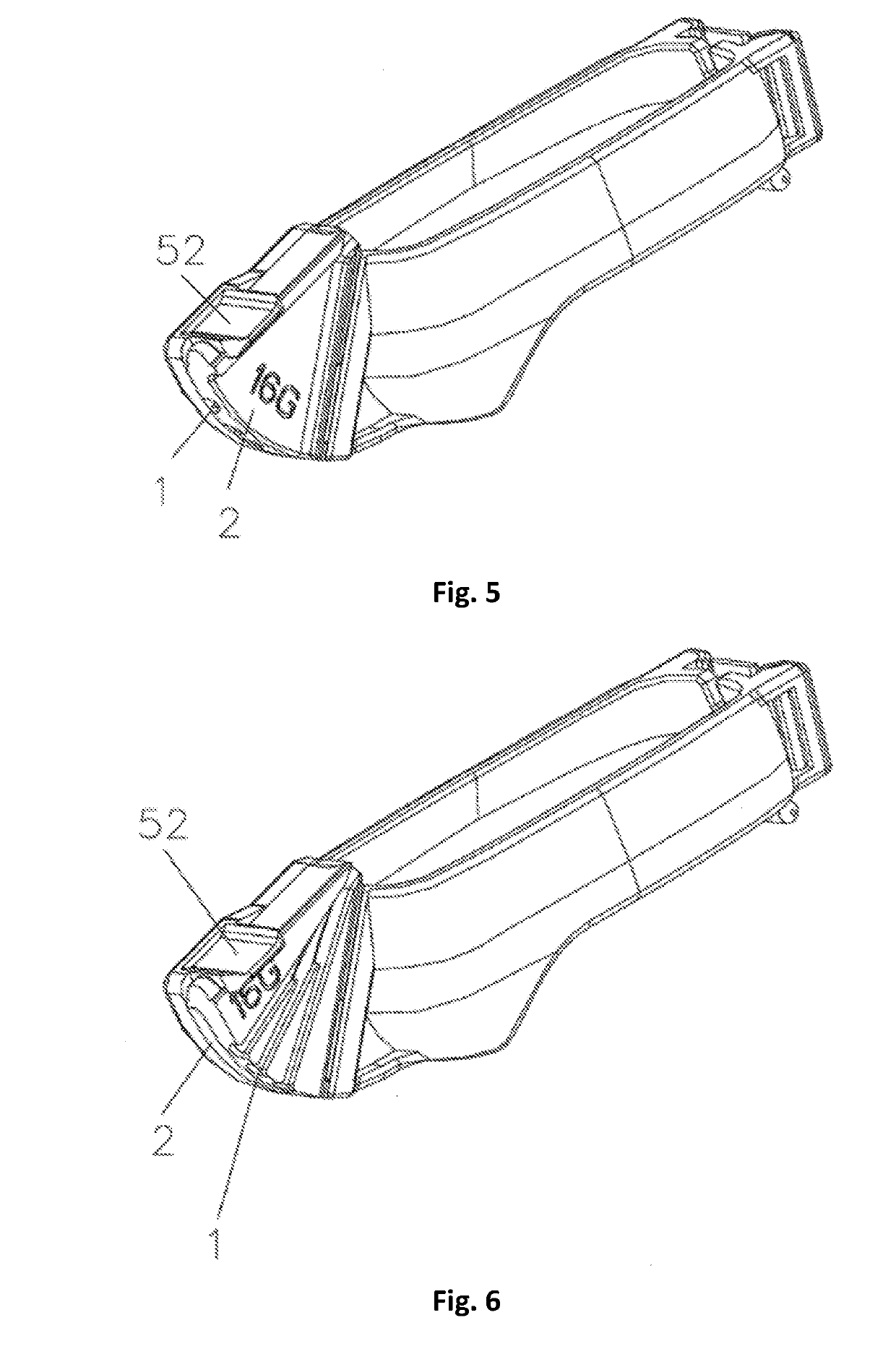
The present invention provides a double-sided needle groove, a frame body, and a puncture frame that can be used in B-ultrasound puncture operations. The needle groove has one or more needle slots with fixed or adjustable needle insertion angles that can accommodate different types of puncture needles and reduce the number of accessories. The puncture frame separates the needle groove and the frame body, allowing for adjustable needle insertion angle. The needle slot surface with either a fixed or adjustable angle can be used for various B-ultrasound puncture operations. The double-sided needle groove fast installs, saves resources, and reduces costs in B-ultrasound puncture operations.

Problems solved by technology

Therefore, the increase in the accessories would increase costs in the B-ultrasound puncture operation of a patient and waste resources.

Method used


Image

  • Double-sided needle groove, frame body and puncture frame
  • Double-sided needle groove, frame body and puncture frame
  • Double-sided needle groove, frame body and puncture frame

Examples


Embodiment Construction

[0024]Hereinafter, the structures of the present invention will be explained in detail with reference to the figures.

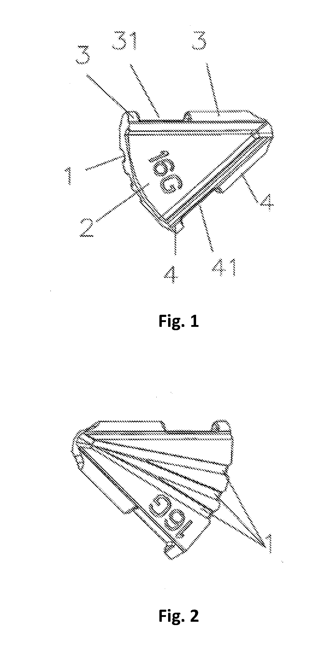
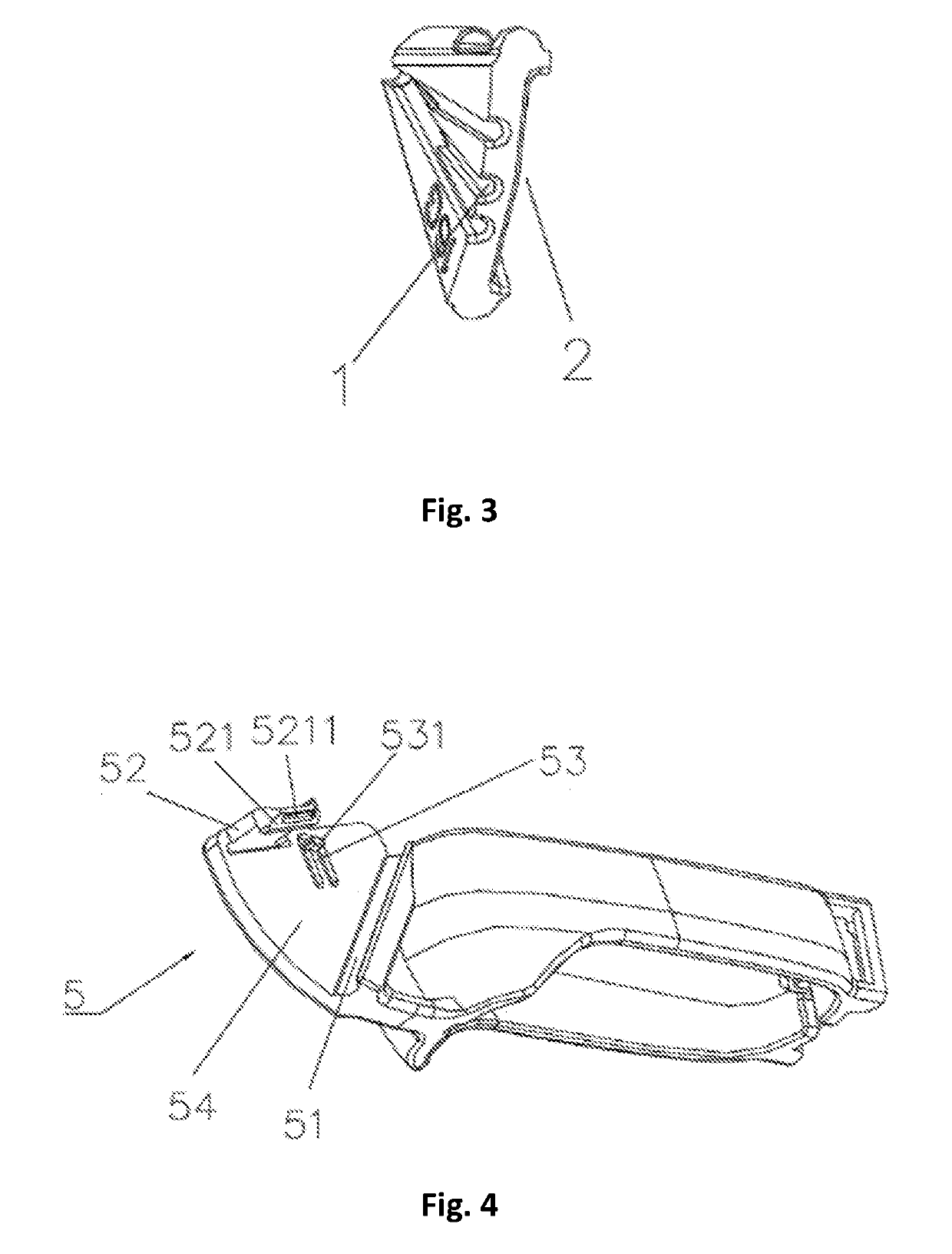
[0025]As shown in FIGS. 1-3, the present invention provides a double-sided needle groove, wherein the double-sided needle groove, which has a “fan-like” outer contour, is provided at one side with three needle slots al, and the three needle slots al may be designed to meet multiple specifications so that apertures thereof are in one-to-one correspondence to the diameters of puncture needles; and the double-sided needle groove is provided at the other side with one fan-shaped (a certain angle range may be provided) needle slot h2, and the needle slot b2 may be designed to meet multiple width specifications so that dimensions thereof are in one-to-one correspondence to the diameters of the puncture needles.

[0026]The double-sided needle groove of the present invention is provides a rotating convex half shaft a3 and a rotating convex half shaft b4, on each side respective...


PUM


Abstract

A double-sided needle groove, a frame body and a puncture frame, wherein the double-sided needle groove has an axisymmetric outer contour, and is provided at one side with at least one needle slot a (1) and at the other side with at least one needle slot b (2); and the needle slot b (2) is fan-shaped. The double-sided needle groove is provided with one or more needle slots a (1) having a fixed needle insertion angle and a needle slot b (2) having an adjustable needle insertion angle, and the needle slot a (1) and the needle slot b (2) respectively correspond to the diameters of puncture needles and may be designed to meet multiple width specifications. During the performance of a B-ultrasound puncture operation, based on operation requirements of a surgeon for a fixed or adjustable angle, there is only a need to switch front and back sides of the double-sided needle groove, thus avoiding the need for an additional puncture frame, and switch the needle slots according to the diameters of the puncture needles. As can be seen, the double-sided needle groove can be applied to various types of B-ultrasound puncture operations and can effectively reduce the number of accessories in the puncture operations, thereby providing fast installation, saving resources and reducing costs.

Description

FIELD OF THE INVENTION[0001]The present invention relates to the technical field of in vitro puncture frames required for ultrasonic B-ultrasound puncture operations, and specifically relates to a double-sided needle groove, a frame body and a puncture frame.TECHNICAL BACKGROUND[0002]The current in vitro puncture frames generally control the needle insertion in two ways: 1. using a rotating needle slot structure; and 2. using a single needle groove structure. The single needle groove generally has two forms: 1. a needle groove directly having a fixed needle insertion angle; and 2, a needle groove with adjustable needle insertion angle. Both of the needle grooves have apertures of different specifications for one-to-one correspondence to puncture needles of different diameters, so each puncture frames using the single needle groove structure must be equipped with needle grooves of various aperture specifications. In a B-ultrasound puncture operation, the surgeon would select, accordi...

Claims


Application Information

Patent Timeline
IPC IPC(8): A61B17/34
CPCA61B17/3403A61B2017/3411A61B2017/3413A61B90/11A61B17/34
Inventor WANG, QIN
Owner WANG QIN
Learn More