Insulation Material Arrangement

a technology of material arrangement and arrangement, applied in the direction of film/foil adhesive primer layer, film/foil adhesive, heat storage plant, etc., can solve the problems of limiting the materials that may be applied to the pcm, difficult and/or costly manufacturing, and requiring additional waiting tim

Inactive Publication Date: 2019-05-23
SCHMETZER IND HLDG PTY LTD
View PDF0 Cites 3 Cited by
  • Summary
  • Abstract
  • Description
  • Claims
  • Application Information

AI Technical Summary

Problems solved by technology

A problem with this insulation material relates to ease and speed of use and, in particular, the ease and speed of application of this insulation material to surfaces within a building such as vertical walls, the underside of surfaces or wrapping around corners.
Another problem with this insulation material is that it may be difficult and / or costly to manufacture as it requires heating to liquefy the PCM before applying the PCM to the insulation sheets.
The heating may also limit the materials that may be applied to the PCM during manufacture, require additional waiting time or the heating may damage or limited the types of the PCM used.
Yet another problem with this insulation material is that the material may need to be relatively thick to achieve desirable the insulative properties.
Another problem encountered when dealing with phase change materials is their flammability.
There are concerns about leakage, volume expansion, and / or flammability associated with the use of hydrocarbon PCMs.

Method used


Image

  • Insulation Material Arrangement
  • Insulation Material Arrangement

Examples


Embodiment Construction

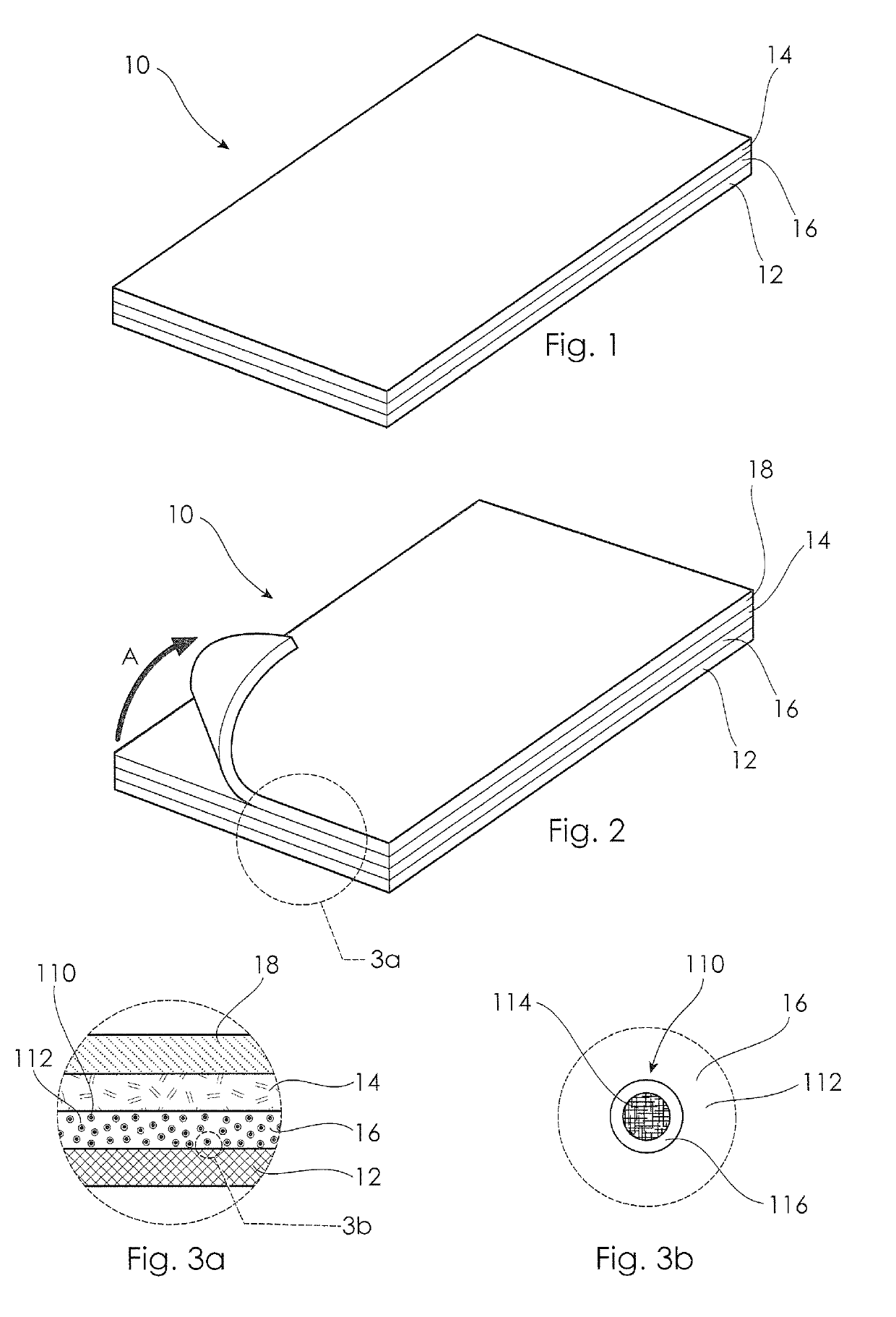
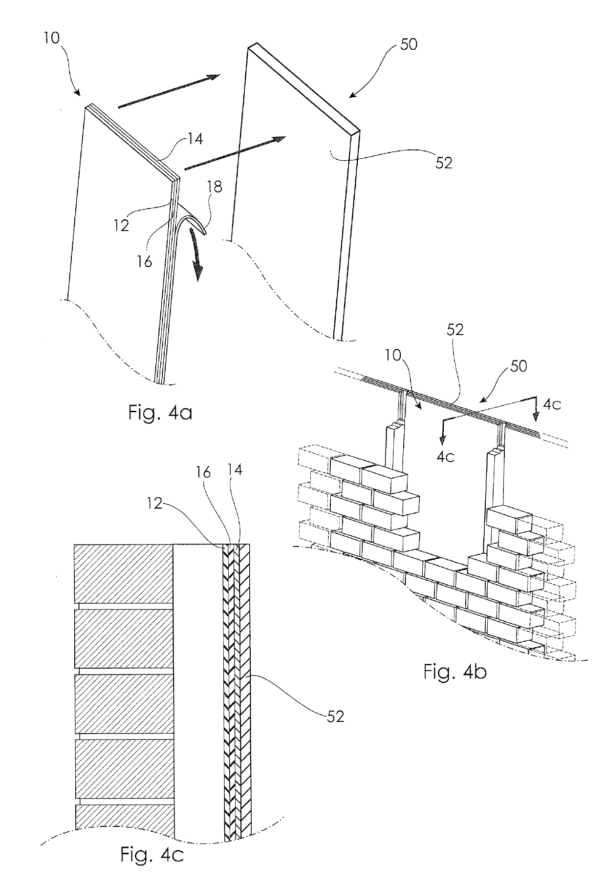
[0041]Referring to FIG. 1, there is shown a material arrangement 10 for insulating a building structure 50 such as a wall 52 (shown in FIG. 4b). The material arrangement 10 includes a planar backing layer 12, a planar adhesive layer 14 (co-planar with the backing layer 12) and a planar phase change material (“PCM”) layer 16 which is arranged between the backing layer 12 and the adhesive layer 14, and is also co-planar therewith. The material arrangement 10 shown in FIG. 1 is of exemplary length and width to illustrate the cross-sectional layer arrangement, and can be manufactured as a multi-layer sheet, panel or elongate strip form in any suitable continuous length, having a width which is subject only to the width of the machine used to form the multi-layer material arrangement 10.

[0042]The adhesive layer 14 includes a pressure sensitive adhesive adapted to secure the material arrangement 10 to the structure 50 in a fitted condition in which the adhesive layer is contacted with, or...


PUM

PropertyMeasurementUnit
thicknessaaaaaaaaaa
thicknessaaaaaaaaaa
temperatureaaaaaaaaaa

Abstract

An insulating material arrangement (10) is disclosed for insulating a building structure (50) such as a wall (52). The material arrangement (10) includes a planar backing layer (12), a planar adhesive layer (14) co-planar with the backing layer (12) and a planar phase change material (“PCM”) layer (16) which is arranged between the backing layer (12) and the adhesive layer (14), and is also co-planar therewith. The adhesive layer (14) is adapted to secure the material arrangement (10) to the structure in a fitted condition in which the adhesive layer (14) is contacted with the building structure (50). The PCM layer (16) is formed of a silicone foam polymer that is impregnated in some embodiments with micro-encapsulated phase change material in the form of beads, shells or granules (110), and in another arrangement, the PCM layer can also comprise a silicone foam polymer that is impregnated with a phase change material which is absorbed into an amount of porous, inorganic, finely-sized particulate solids (a so-called “bound PCM”).

Description

TECHNICAL FIELD[0001]This disclosure relates to an insulation material arrangement, in particular, such as arrangement including a phase change material.BACKGROUND OF THE DISCLOSURE[0002]Insulation is desirable, and often required, to be placed in building structures such as insulating a wall, roof or ceiling. Accordingly, various types of insulation materials have been proposed including those that include phase change materials.[0003]Phase change materials are materials that change phase to absorb or release heat, causing a change in the “state” or “base” of the materials. For example, in one type of these, the phase change materials are transformed between a solid and a liquid form. Generally, the heat applied to a phase change material is “consumed” by the material during its conversion from solid state to liquid state while the phase change material maintains a substantially constant temperature. In reverse, the heat that was absorbed by the change to the liquid phase is releas...

Claims


Application Information

Patent Timeline
Patent Type & Authority Applications(United States)
IPC IPC(8): E04B1/80E04B1/94E04B1/76B32B5/18B32B7/06B32B7/12B32B25/06B32B5/02B32B5/26B32B25/08B32B25/20C09J7/38C09J7/50C09J7/21C09J7/40C09J11/04C09J5/00C09J11/08C09K21/14C09K5/06F28D20/02
CPCE04B1/80E04B1/948E04B1/7675B32B5/18B32B7/06B32B7/12B32B25/06B32B5/02B32B5/26B32B25/08B32B25/20C09J7/38C09J7/50C09J7/21C09J7/405C09J11/04C09J5/00C09J11/08C09K21/14C09K5/063F28D20/023E04B2001/742B32B2266/0207B32B2307/304B32B2250/04C09J2205/106C09J2205/11C09J2400/263C09J2400/123C09J2483/003Y02B10/20B32B29/007B32B2250/02B32B2419/00C08L83/04E04B1/78F24S21/00Y02E10/40Y02E60/14B32B3/00C09K5/06B32B5/00C09J2301/41C09J2301/412
Inventor SCHMETZER, BRETT ANTHONYSCHMETZER, STEVEN JOHN
Owner SCHMETZER IND HLDG PTY LTD
Why Eureka
Try Eureka