Turbine and Turbocharger

a turbocharger and turbine technology, applied in the direction of engines, machines/engines, engine components, etc., can solve the problems of failure of the turbine b>2/b>, achieve the effect of improving burst protection, cost and weight advantages, and thin wall thickness

Active Publication Date: 2019-05-23
MAN ENERGY SOLUTIONS SA
View PDF0 Cites 2 Cited by
  • Summary
  • Abstract
  • Description
  • Claims
  • Application Information

AI Technical Summary

Benefits of technology

[0008]There is a need for improving the burst protection through turbine-internal measures, in order for e

Problems solved by technology

During the operation, a failu

Method used


Image

  • Turbine and Turbocharger
  • Turbine and Turbocharger

Examples


Embodiment Construction

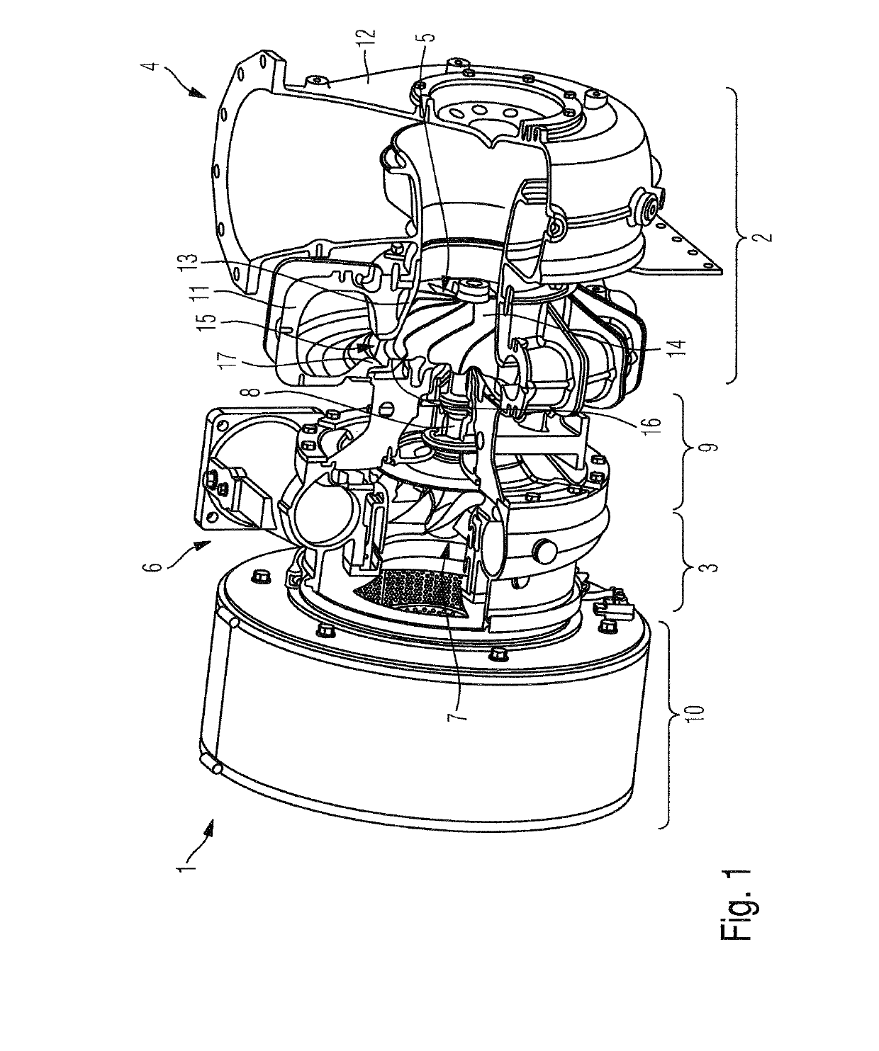
[0017]The invention present here relates to a turbine and to a turbocharger. The fundamental construction of a turbine and of a turbocharger according to the prior art has already been described making reference to FIG. 1. In the following, only such details of a turbine according to the invention and of a turbocharger according to the invention, by which the turbine differs from the prior art, will be discussed.

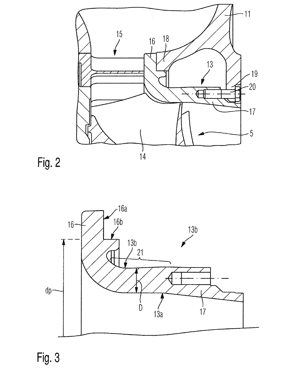
[0018]FIGS. 2 and 3 show details of a turbine of a turbocharger according to one aspect of the invention, wherein FIG. 1 shows an extract in the region of the insert piece 13, of the adjoining nozzle ring 15 and of the adjoining inflow housing 11 of the turbine housing 4.

[0019]The insert piece 13 extends radially adjoining the moving blades 14 of the turbine rotor 5 and delimits, at least in sections, a flow passage of the turbine 2.

[0020]At an upstream end, the insert piece 13 comprises a first flange 16 and at a downstream end, a second flange 17.

[0021]At the first flange ...


PUM


Abstract

A turbine for a turbocharger, for expanding a medium, with a turbine rotor, having a turbine housing with an insert piece, which runs radially outside of the adjoining blades of the turbine rotor. The insert piece at an upstream end, includes a first flange and a second flange at a downstream end. The insert piece, in a middle section, which extends between the first flange and the second flange, has an approximately constant thickness.

Description

BACKGROUND OF THE INVENTION1. Field of the Invention[0001]The invention relates to a turbine and to a turbocharger having a turbine.2. Description of the Related Art[0002]FIG. 1 shows the fundamental construction of a turbocharger 1 known from the prior art.[0003]The turbocharger 1 comprises a turbine 2 for expanding a first medium, in particular for expanding exhaust gas of an internal combustion engine. Turbocharger 1 furthermore comprises a compressor 3 for compressing a second medium, in particular charge air, namely utilising energy extracted in the turbine 2 during the expansion of the first medium.[0004]The turbine 2 comprises a turbine housing 4 and a turbine rotor 5. The compressor 3 comprises a compressor housing 6 and a compressor rotor 7. The compressor rotor 7 is coupled to the turbine rotor 5 via a shaft 8, which is mounted in a bearing housing 9. The bearing housing 9 is positioned between the turbine housing 4 and the compressor housing 5 and is connected both to the...

Claims


Application Information

Patent Timeline
IPC IPC(8): F01D25/24F02C6/12F01D25/16
CPCF01D25/243F02C6/12F01D25/16F05D2220/40F01D9/00F01D9/045F01D9/02F01D25/24F02B37/10Y02T10/12
Inventor BRAUN, STEFFENKLIMA, JIRIHORT, VLADIMIRWEISBROD, TOBIASHAAS, BERNDNIEBUHR, JOHANNES
Owner MAN ENERGY SOLUTIONS SA
Why Eureka
Try Eureka