Turbofan comprising a low-supercritical-pressure shaft

a supercritical pressure, shaft technology, applied in the direction of engines/engines, machines/engines, engine fuction, etc., can solve the problems of uncontrolled increase, rapid degradation of the critical speed of the turbine at stabilised speed, and overloading of the engine structure, so as to achieve the dynamic response of the shaft beyond the critical speed, and the effect of reducing the number of turns

Active Publication Date: 2019-05-23
SN DETUDE & DE CONSTR DE MOTEURS DAVIATION S N E C M A
View PDF0 Cites 25 Cited by
  • Summary
  • Abstract
  • Description
  • Claims
  • Application Information

AI Technical Summary

Benefits of technology

[0013]An aim of the invention is therefore to propose a bypass turbofan engine and at high dilution rate, which has a sound dynamic situ...

Problems solved by technology

A turbomachine turning at a critical speed at stabilised speed risks rapid degradation.
Also, the second flexural deformation mode of the lowpressure shaft, called mode 2f, occurs at a critical speed of the order of 11000 rpm, which is too close to the redline and results in overloading of the engine structure.
In fact, the a...

Method used


Image

  • Turbofan comprising a low-supercritical-pressure shaft
  • Turbofan comprising a low-supercritical-pressure shaft

Examples


Embodiment Construction

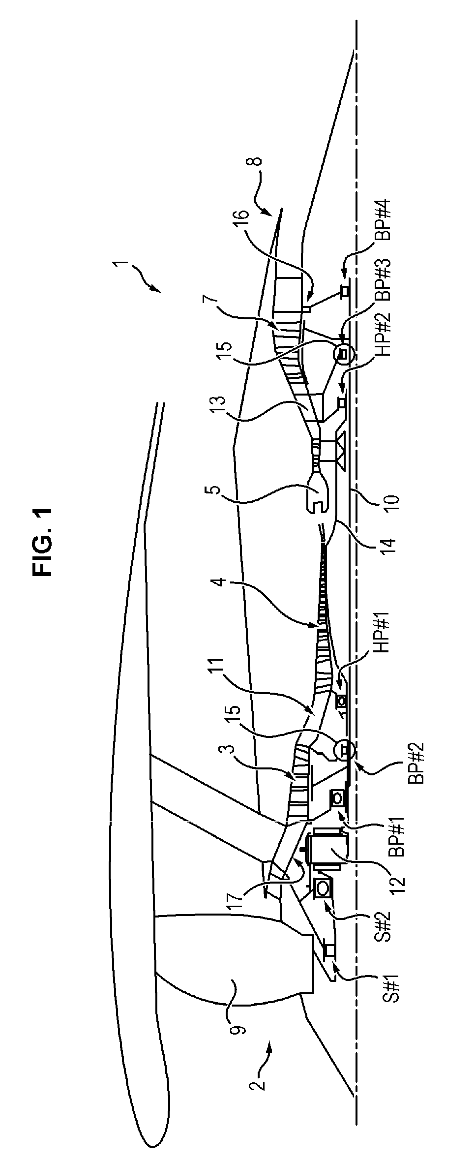
[0037]In the following, a turbofan engine 1 will now be described in reference to the attached figures.

[0038]The turbofan engine 1 conventionally comprises a fan 2 and a primary body. In the direction of flow of gases the primary body comprises a lowpressure compressor 3, a highpressure compressor 4, a combustion chamber 5, a high pressure turbine 6, a lowpressure turbine 7 and a discharge nozzle 7 for gas.

[0039]The fan 2 comprises a fan disc 2 provided with fan blades 9 on its periphery, which, when set in rotation drive the airflow in the primary and secondary flow spaces of the turbofan engine 1. The disc fan 2 is supported by a lowpressure shaft 10 which is driven in rotation by the lowpressure turbine 7.

[0040]The turbofan engine 1 also comprises an intercompressor housing 11 whereof the hub is arranged between the housing of the lowpressure compressor 3 and the housing of the highpressure compressor 4.

[0041]The turbofan engine 1 has a high dilution rate, that is, a dilution rat...


PUM


Abstract

A turbofan engine including: a turbine shaft; a fan shaft; and a reduction mechanism coupling the turbine shaft and the fan shaft, is provided. The turbofan engine has a bypass ratio greater than or equal to 10, and the turbine shaft is supported by four bearings such that the flexural deformation modes of the turbine shaft are positioned in transient phase or outside the operating range of the turbofan engine.

Description

FIELD OF THE INVENTION[0001]The invention relates to the field of turbomachines, and more particularly bypass turbofan engines having a high, or even very high, dilution rate and a supercritical lowpressure shaft, that is, with a flexural deformation mode in the operating range.TECHNOLOGICAL BACKGROUND[0002]A bypass turbofan engine generally comprises, from upstream to downstream in the direction of the flow of gases, a ducted fan housed in a fan housing, a primary annular flow space and a secondary annular flow space. The air mass suctioned by the fan is therefore divided into a primary flow, which circulates in the primary flow space, and a secondary flow, which is concentric with the primary flow and circulates in the secondary flow space.[0003]The primary flow space passes through a primary body comprising one or more compressor stages, for example a lowpressure compressor and a high pressure compressor, a combustion chamber, one or more turbine stages, for example a highpressur...

Claims


Application Information

Patent Timeline
IPC IPC(8): F02K3/06F02C7/06
CPCF02K3/06F02C7/06F05D2220/326F05D2220/327F05D2260/40311
Inventor DIEVART, JEREMYBENSLAMA, YANISNOWAKOWSKI, NATHALIE
Owner SN DETUDE & DE CONSTR DE MOTEURS DAVIATION S N E C M A
Why Eureka
Try Eureka