System and method for detecting a lubricant-out condition in an aircraft gearbox

a technology of lubricant-out condition and aircraft gearbox, which is applied in the field of aircraft, can solve problems such as unplanned landing or undesirable landing

Active Publication Date: 2019-05-23
SIKORSKY AIRCRAFT CORP
View PDF0 Cites 2 Cited by
  • Summary
  • Abstract
  • Description
  • Claims
  • Application Information

AI Technical Summary

Benefits of technology

[0008]In addition to one or more of the features described above or below, or as an alternative, further embodiments could include wherein the at least two non-pressure based parameters include temperature and conductivity.
[0009]In addition to one or more of the features described above or below, or as an alternative, further embodiments could include wherein the gearbox comprises a splash lubricated gearbox.

Problems solved by technology

Failure of such a system may lead to an undesirable or unplanned landing.

Method used


Image

  • System and method for detecting a lubricant-out condition in an aircraft gearbox
  • System and method for detecting a lubricant-out condition in an aircraft gearbox

Examples


Embodiment Construction

[0022]A detailed description of one or more embodiments of the disclosed apparatus and method are presented herein by way of exemplification and not limitation with reference to the Figures.

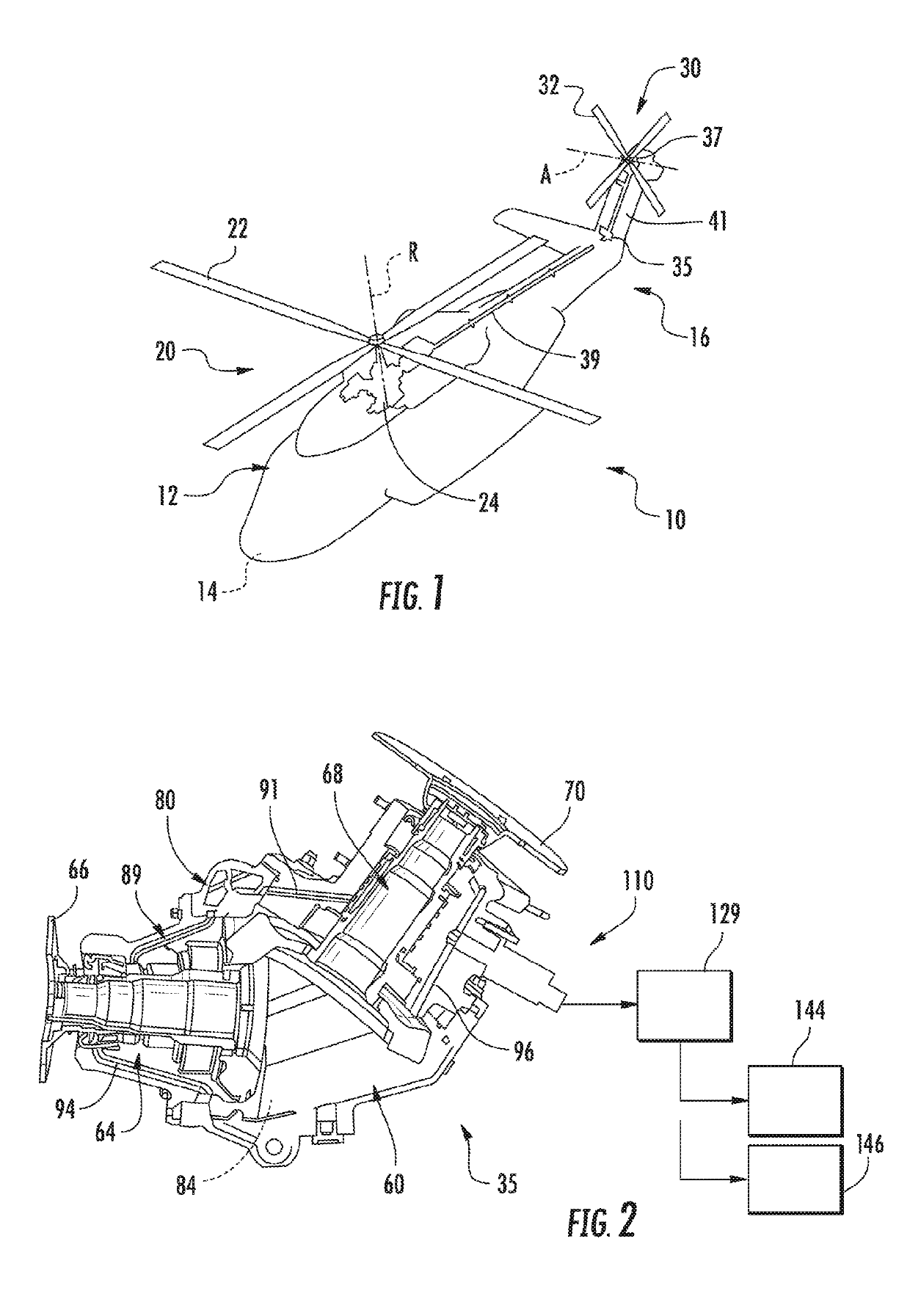
[0023]FIG. 1 schematically illustrates a rotary wing aircraft 10 having an airframe 12 including a nose 14 and an extending tail 16. Airframe 12 supports a main rotor assembly 20 including a plurality of rotor blades, one of which is indicated at 22. Main rotor assembly 20 is driven by an engine 24 to rotate about a main rotor axis “R”. Aircraft 10 also includes a tail rotor assembly 30 including a plurality of tail rotor blades 32. Tail rotor assembly 30 is mounted to extending tail 16 and operatively connected to engine 24. More specifically, tail rotor system 30 is connected to engine 24 through a first gearbox 35 and a second gearbox 37. A first driveshaft 39 mechanically links engine 24 and first gearbox 35. A second drive shaft 41 mechanically links first gearbox 35 with second gearbox 37. ...


PUM

PropertyMeasurementUnit
temperatureaaaaaaaaaa
conductivityaaaaaaaaaa
pressureaaaaaaaaaa

Abstract

A gearbox includes a housing including a lubricant reservoir, at least one gear system arranged in the housing, at least one lubricant delivery passage operable to direct a flow of lubricant from a lubricant reservoir onto the at least one gear system, at least one lubricant return passage operable to guide the flow of lubricant to the lubricant reservoir, and a lubricant-out sensor fluidically connected to the at least one lubricant return passage. The lubricant-out sensor is operable to detect a non-pressure based parameter of the lubricant.

Description

BACKGROUND[0001]Exemplary embodiments pertain to the art of aircraft and, more particularly, to a system and method for detecting a lubricant-out condition in an aircraft gearbox.[0002]Aircraft includes a number of systems that promote proper flight conditions. Failure of such a system may lead to an undesirable or unplanned landing. Accordingly, manufactures design aircraft with a capability to maintain flight for a period of time following a system failure. The period of time may vary for particular aircraft. Military aircraft should be capable of sustained safe flight for a period of time following a ballistic impact to the system.BRIEF DESCRIPTION[0003]Disclosed is a gearbox including a housing including a lubricant reservoir, at least one gear system arranged in the housing, at least one lubricant delivery passage operable to direct a flow of lubricant from a lubricant reservoir onto the at least one gear system, at least one lubricant return passage operable to guide the flow ...

Claims


Application Information

Patent Timeline
Patent Type & Authority Applications(United States)
IPC IPC(8): F16N29/04F16N29/02B64C27/16F16H57/04G01N33/28B64D45/00
CPCF16N29/04F16N29/02B64C27/16F16H57/0457G01N33/2888B64D45/00B64D2045/0085F16N2250/18F16N2250/08B64C27/14F16N7/00F16N29/00G01F23/22G01F23/24G01F23/246F16H57/0449F16H57/0424
Inventor GLASSER, ADAM R.WINT, DWAINEBALDYGA, JOHN J.MULLEN, MICHAEL F.LUTIAN, DAVID M.MCKAN, LINDSEY
Owner SIKORSKY AIRCRAFT CORP
Why Eureka
Try Eureka