
Bus Bar Module and Wire Harness

a technology of wire harnesses and modules, applied in the direction of cables, flat/ribbon cables, batteries, etc., can solve the problems of weak holding power, insulator resin parts may be broken, and the desired value of holding power cannot be maintained

Inactive Publication Date: 2019-05-23
YAZAKI CORP
View PDF0 Cites 4 Cited by
  • Summary
  • Abstract
  • Description
  • Claims
  • Application Information

AI Technical Summary

Benefits of technology

The patent text describes a bus bar module that can hold an insulator resin part, a bus bar, and a wire harness securely. The module prevents the insulator resin part from sagging due to its weight and ensures good attachment of the bus bar to the battery pack. The bus bar is designed to have good workability and manageability in the space where it is mounted. The technical effects of the patent text are improved holding strength of the insulator resin part, prevention of extreme deterioration of the attachment property, and suppression of deterioration of workability and management of the bus bar.

Problems solved by technology

However, in such a bus bar module, when the insulator resin part is thinned, a holding power is weak when the bus bar is crimped and connected.
Thus, when an impact is applied, the insulator resin part may be possibly broken to detach the bus bar from the insulator resin part.
Further, when the value obtained by dividing the thickness of the insulator resin part by the thickness of the bus bar is smaller than 0.5, the insulator resin part is too thin to the bus bar, so that the desired value of the holding power may not be possibly maintained.
In addition thereto, when the above-described value exceeds 2.38, the insulator resin part is too thick to the bus bar and a crimping work is difficult so that the crimping work may be incomplete and the desired value of the holding power may not be probably maintained.
According to the aspect (2), when the sectional area of the insulator resin part is large, the insulator resin part sags due to its deadweight relative to the plane on which the conductor wires of the cable part are respectively arranged, so that an attaching property is deteriorated when the bus bar is fixed to the battery pack.
Further, when the thickness of the bus bar exceeds 1.5 mm, a management of the bus bar in a space in which the bus bar is mounted is deteriorated.

Method used


Image

  • Bus Bar Module and Wire Harness
  • Bus Bar Module and Wire Harness
  • Bus Bar Module and Wire Harness

Examples


Embodiment Construction

[0026]Now, the present invention will be described below by referring to a preferred exemplary embodiment. The present invention is not limited to a below-described exemplary embodiment and may be suitably changed within a scope which does not depart from the gist of the present invention. Further, in the below-described exemplary embodiment, an illustration or an explanation of a structure is partly omitted. However, it is to be understood that to a detail of the omitted technique, a well-known or conventional technique is applied within a range in which a contradiction to below-described contents does not occur.

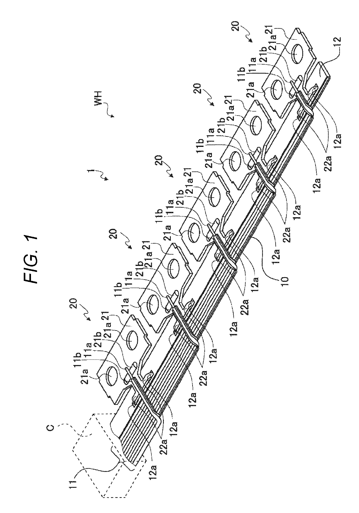
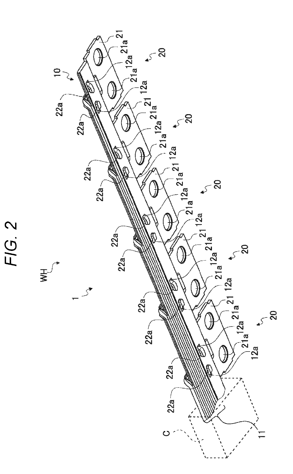
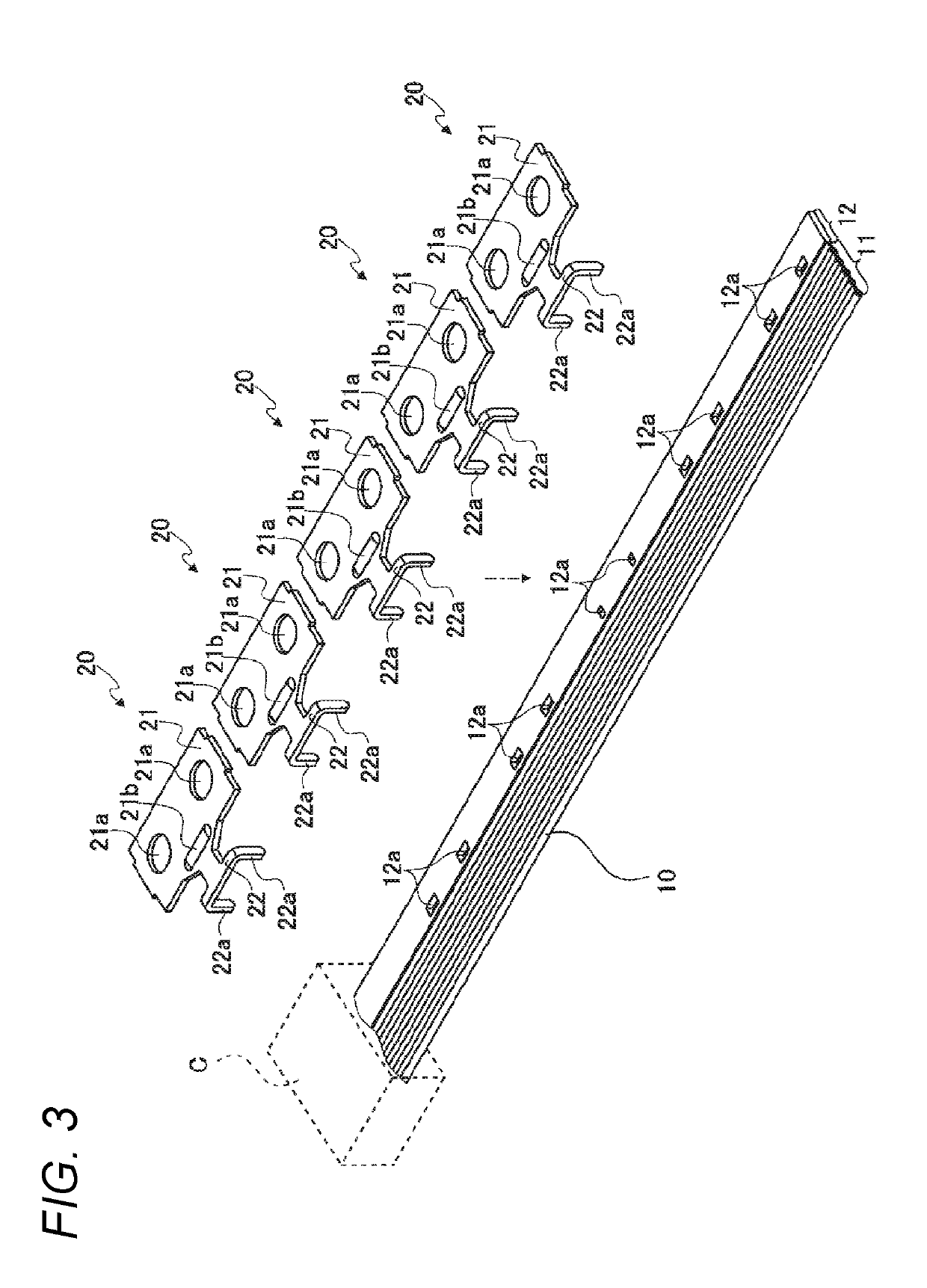
[0027]FIG. 1 is a perspective view of an upper surface of a wire harness including a bus bar module according to an exemplary embodiment of the present invention. FIG. 2 is a perspective view of a lower surface of the wire harness including the bus bar module according to the exemplary embodiment of the present invention. As shown in FIG. 1 and FIG. 2, the wire harness WH i...


PUM

PropertyMeasurementUnit
thicknessaaaaaaaaaa
areaaaaaaaaaaa
thicknessaaaaaaaaaa

Abstract

A bus bar module includes a flat cable having a cable part and an insulator resin part and a bus bar crimped and fixed to the insulator resin part. The cable part includes a plurality of conductor wires arranged in parallel at predetermined intervals on a plane and a covering part integrally covering the plurality of conductor wires with an insulating resin. The insulator resin part is disposed in parallel to the cable part on the plane and made of a same resin as the insulating resin of the covering part.

Description

CROSS REFERENCE TO RELATED APPLICATIONS[0001]This application claims priority from Japanese Patent Application No. 2017-221502 filed on Nov. 17, 2017, the entire contents of which are incorporated herein by reference.BACKGROUND OF THE INVENTIONField of the Invention[0002]The invention relates to a bus bar module and a wire harness.Description of Related Art[0003]As a battery mounted on a hybrid motor vehicle or an electric vehicle, a battery module is known. The battery module is formed in such a way that a plurality of battery cells are laminated in a direction of thickness and the laminated battery cells are accommodated in a case. As the battery cell, for instance, a lithium ion battery or a secondary battery is used. In the battery module, bus bars which electrically connect electrode terminals of the individual battery cells together or voltage detection wires which detect the states of voltages of the individual battery cells are provided.[0004]In order to achieve an electric ...

Claims


Application Information

Patent Timeline
Patent Type & Authority Applications(United States)
IPC IPC(8): H01M2/20H01B7/08H01M2/10H01M2/02H01M50/528H01M50/503H01M50/507H01M50/569
CPCH01M2/202H01B7/08H01M2/1083H01M2/0277H01B7/009H01B7/0823H01M10/482H01M2220/20Y02E60/10H01M50/507H01M50/569H01M50/503
Inventor OSHIMA, TAKESHI
Owner YAZAKI CORP
Learn More