
Medical Needle System

a needle system and needle technology, applied in the field of spinal needles, can solve the problems of high incidence of cerebrospinal fluid escape, inability to puncture the dura, uncertain negative side effects, etc., and achieve the effect of reducing the loss of spinal fluid

Inactive Publication Date: 2019-05-30
CAMERON BLAINE S
View PDF3 Cites 1 Cited by
  • Summary
  • Abstract
  • Description
  • Claims
  • Application Information

AI Technical Summary

Benefits of technology

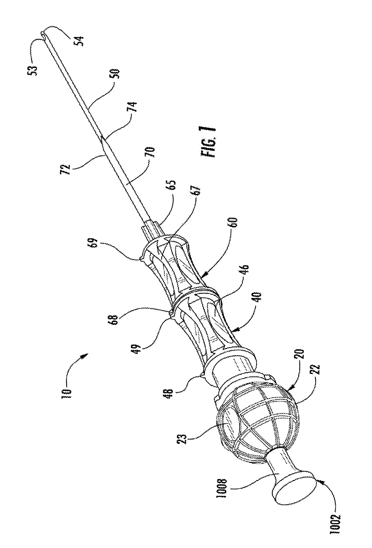
The present invention provides a spinal needle with a one-way valve to prevent loss of spinal fluid during the transition from the removal of a stylet that is then replaced by the injection of spinal anesthesia from the needle body and delivered to a patient's spine. The needle also reduces cerebrospinal fluid loss and allows visually confirmation of the proper placement of the needle inside the patient. Additionally, the invention includes a medical needle system with an introducer and a stylet that can engage and disengage within the medical needle cannula, a retaining body with a window for viewing bodily fluid contents, and a detection member that changes color when in contact with bodily fluid.

Problems solved by technology

However, there are certain negative side effects that occur following a puncture to the dura.
Further, during the transition between the spinal needle and the catheter, there is a high incidence of cerebrospinal fluid escape.
The dura and the arachnoid are in close contact that usually it is not possible to puncture the dura without also piercing the arachnoid.
Nevertheless, on rare occasions, the tip of the conventional epidural or spinal needle may accidentally enter the subdural space.
Local anesthetic inadvertently injected into the subdural space will diffuse poorly and result in inadequate contact with the nerve roots.
Poor or absent anesthesia may ensue.
Should subdural placement occur during an attempted epidural anesthetic, the improper position of the needle may not be recognized and the injection of an epidural dose of local anesthetic may result in a much higher block than anticipated.
However, the incidence of postspinal headache is increased with the larger needle, particularly if the larger needle is also equipped with a standard point which is a cutting bevel.
Bringing the patient into the erect position also results in traction on the pain-sensitive, dilated blood vessels.
There is currently no adequate spinal needle system or device capable of sufficiently reducing the loss of cerebrospinal fluid escape following the transition between the spinal needle and the catheter.
Nor is there an adequate needle for indicating cerebral spinal fluid contained within the body of the needle.

Method used


Image

  • Medical Needle System
  • Medical Needle System
  • Medical Needle System

Examples


Embodiment Construction

[0031]The present invention advantageously provides a spinal needle constructed to reduce incidence of complications in intrathecal procedures. The present invention contemplates various types of spinal needle bevels, including without limitation Whitacre needles, Sprotte needles, Quincke needles, and Atraucan needles.

[0032]Accordingly, the needle components have been represented where appropriate by conventional symbols in the drawings, showing only those specific details that are pertinent to understanding the embodiments of the present invention so as not to obscure the disclosure with details that will be readily apparent to those of ordinary skill in the art having the benefit of the description herein.

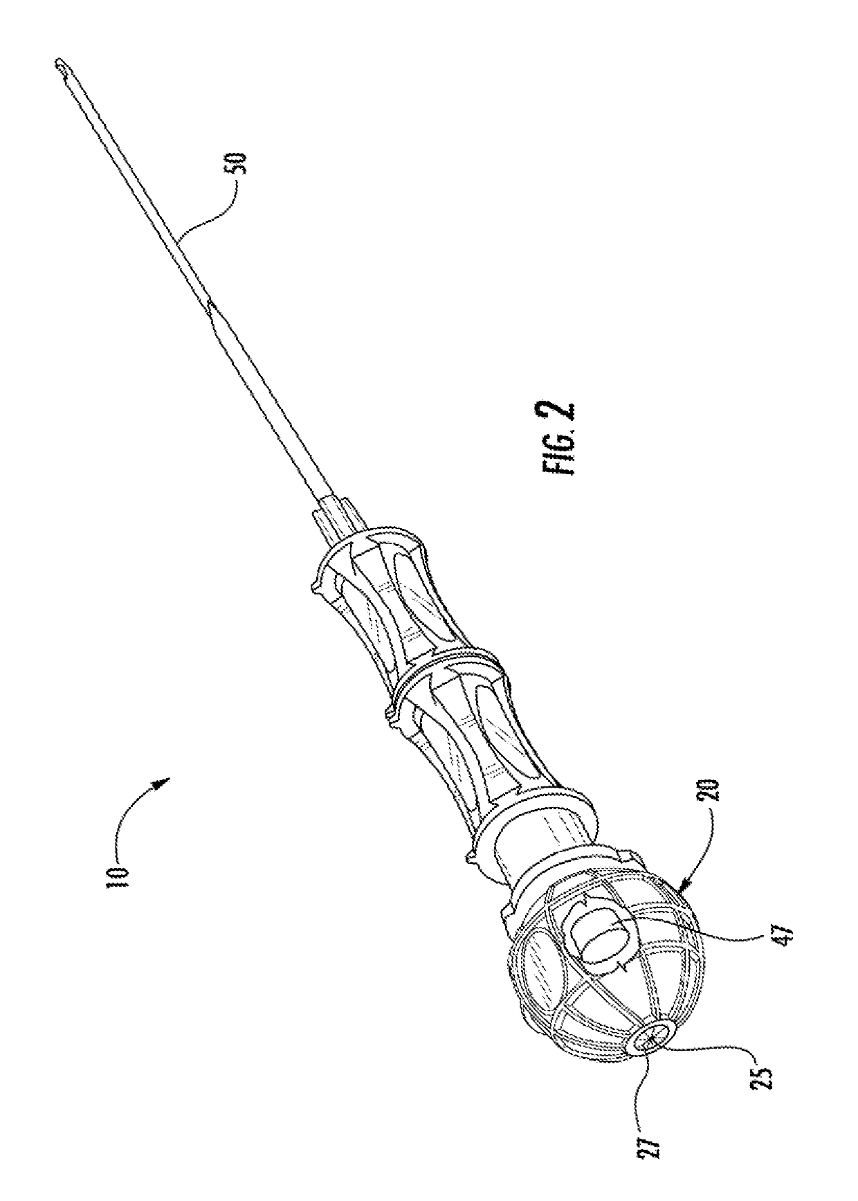
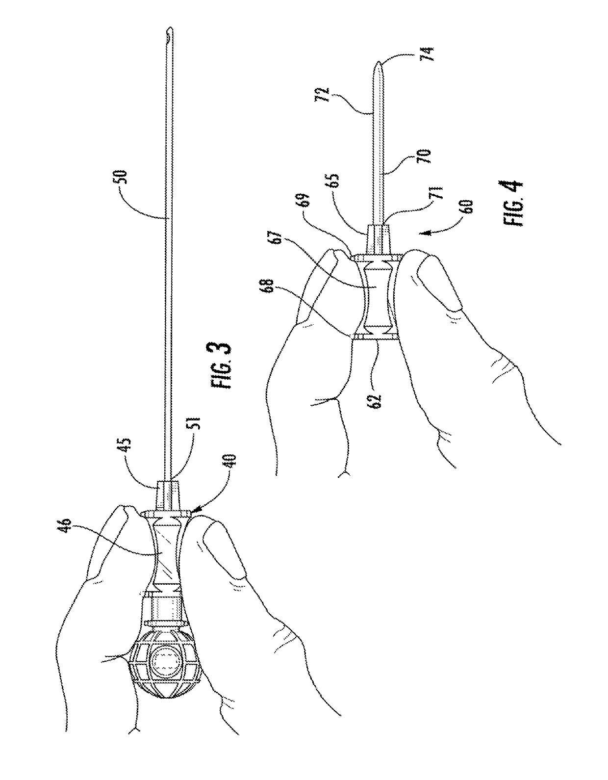
[0033]Referring now to the drawings figures in which like reference designators refer to like elements. FIG. 1 shows an exemplary spinal needle constructed in accordance with the principles of the present invention and designated generally as needle 10. In particular, needle 10 i...


PUM


Abstract

A spinal needle that includes a needle body insertable through tissue to a desired depth within a patient's body, the spinal needle is capable of retaining bodily fluids, including cerebrospinal fluid, and provides a window capable of allowing a user to view the existence or non-existence of bodily fluid retained therein.

Description

FIELD OF THE INVENTION[0001]The present invention relates to a spinal needle, and more particularly to a spinal needle constructed to reduce incidence of complications in intrathecal procedures.BACKGROUND OF THE INVENTION[0002]Spinal needles have the benefit of supplying a dense neural block that inhibits nerve receptors and provides highly effective pain relief. However, there are certain negative side effects that occur following a puncture to the dura.[0003]One well known complication following spinal anesthesia and other spinal needles is post spinal puncture headache (“PSPH”). PSPH occurs due to dural and arachnoid puncture from a loss of cerebrospinal fluid.[0004]Currently, following puncture of the dura such that the catheter is threaded into the epidural space, the spinal needle is removed. However, during said removal, there is a period in which the cerebrospinal fluid is able to escape prior to the insertion of the catheter. Further, during the transition between the spina...

Claims


Application Information

Patent Timeline
IPC IPC(8): A61B17/34A61M25/06A61M5/32
CPCA61B17/3401A61M25/0606A61M5/3286A61M5/46A61B17/3403A61B17/3417A61B2017/347A61B17/3462A61B2017/00907A61B2090/0807A61B2090/3937A61B2090/3945
Inventor CAMERON, BLAINE S.
Owner CAMERON BLAINE S
Learn More