Scanning reflector system

a reflector and reflector technology, applied in the field of scanning reflector systems, can solve problems such as detriment to the effect of amplitud

Active Publication Date: 2019-05-30
MURATA MFG CO LTD
View PDF0 Cites 4 Cited by
  • Summary
  • Abstract
  • Description
  • Claims
  • Application Information

AI Technical Summary

Benefits of technology

[0013]The disclosure is based on the idea of configuring a feedback circuit to drive the reflector system in a nonlinear range that is conventionally avoided for adverse instabilities, and use a specific phenomenon in frequency response therein to enable image area broadening modulation.

Problems solved by technology

However, the requirement for use of high Q values creates some problems in this respect.
However, small deviations in each of the high-quality oscillation modes still have the detrimental effect to the amplitude, so outside the narrow bandwidth, applicable drive voltages do not enable introduction of a modulation signal that could vary the tilt angle θ within an angle α adequate for 2-dimensional image area resulting from successive 360° scanning rounds.
This means that the large Q-value (narrow bandwidth) creates problems if the mirror tilt angle needs to change rapidly, since the time constant is large and the transient term dies slowly.

Method used


Image

  • Scanning reflector system
  • Scanning reflector system
  • Scanning reflector system

Examples


Embodiment Construction

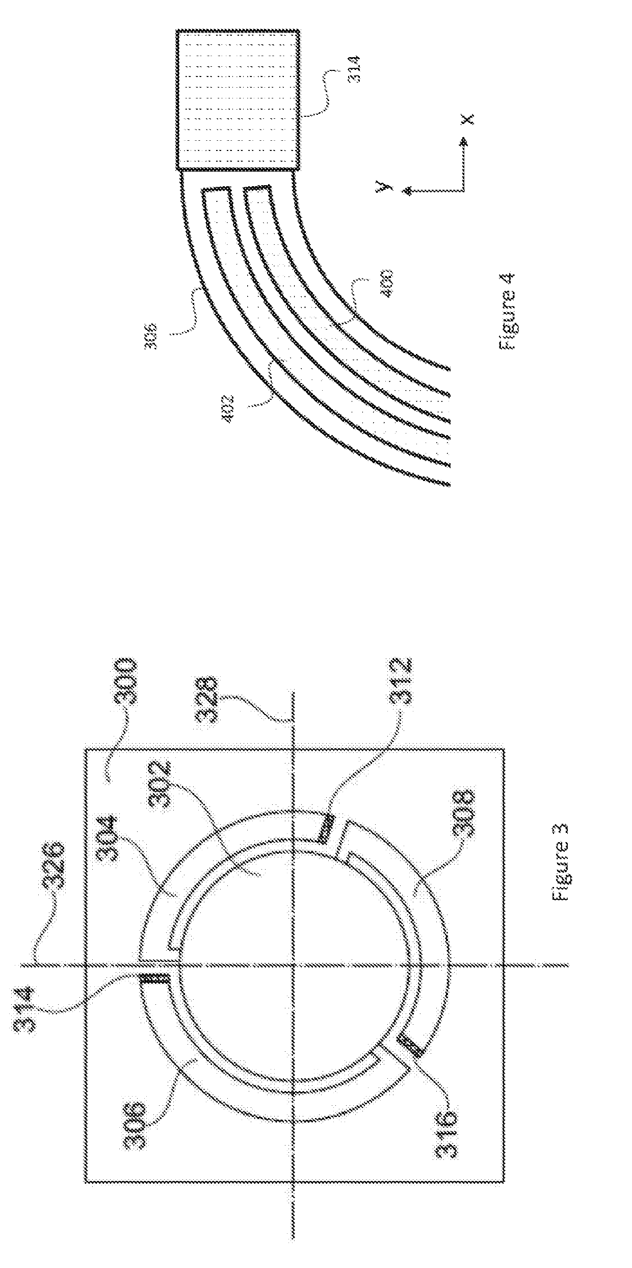
[0024]Embodiments of this disclosure include an apparatus that includes a reflector system and a feedback circuit. FIG. 3 illustrates elements of a reflector system applicable in the disclosed apparatus. The reflector system comprises a support 300, a reflector 302 and a spring structure 304, 306, 308 suspending the reflector from the support for scanning motion of the reflector in two orthogonal oscillation modes.

[0025]The term support 300 refers herein to a mechanical element that may be part of the apparatus that includes the reflector system, for example a part of a MEMS scanning reflector device. Alternatively, the support can be a separate element rigidly fixed to the apparatus. Accordingly, the support represents here any element that provides a rigid, locally inert reference to which other elements of the reflector system can be fixed, or from which other elements of the reflector system can be suspended. The support can, but does not mandatorily include a frame that surroun...


PUM


Abstract

An apparatus includes a reflector system having a support, a reflector and a spring structure for scanning motion of the reflector in two orthogonal oscillation modes. A frequency response peaks at a natural resonant frequency with an initial bandwidth. A first transducer structure provides mechanical actuation of the reflector; a second transducer structure generates sense signals representing mechanical motion of the reflector. A feedback circuit receives from the second transducer structure a sense signal and generates to the first transducer structure a drive signal. The feedback circuit is adjusts amplitude and frequency of the drive signal to a non-linear vibration range where a frequency shift at the peak frequency is at least ten times the initial bandwidth, varies the amplitude of the drive signal in proportion to a waveform of a modulation signal, and sets frequency of the modulation signal component smaller than the frequency shift at the peak frequency.

Description

FIELD OF THE DISCLOSURE[0001]The present disclosure relates to scanning reflector systems, and more particularly to an apparatus and a method enabling scanning motion in two orthogonal oscillation modes.BACKGROUND OF THE DISCLOSURE[0002]Scanning microelectromechanical (MEMS) reflectors can be used in imaging devices such as light-detecting and ranging sensors (LIDARs). A scanning MEMS reflector may contain at least one moving reflector which can reflect light beams from a laser emitter towards the surrounding environment. Additional reflectors or lenses may be included in the light path between the moving reflector and the environment. Returning light beams can be reflected inward towards a photodetector by the same reflectors or lenses which reflected the outgoing beam.[0003]The imaging area (i.e. the field of view) of a scanning MEMS reflector is in part determined by how much and in which way the moving reflector can be tilted. This is illustrated in FIG. 1, which shows a simplif...

Claims


Application Information

Patent Timeline
Patent Type & Authority Applications(United States)
IPC IPC(8): G02B26/08B81B3/00B81B7/02
CPCG02B26/0841B81B3/0083B81B7/02G02B26/0858B81B2201/042G02B26/101G02B26/0833
Inventor LAAKSONEN, TAPANIWJUGA, KONSTAPYNNONEN, MIKKO
Owner MURATA MFG CO LTD
Why Eureka
Try Eureka