Placement device, placement system and placement method

a placement system and placement method technology, applied in the direction of absorbent pads, conveyor parts, undergarments, etc., can solve the problems of possibly not, complicating the device structure, etc., and achieve the effect of increasing the interval between parts and increasing the load on the motor

Active Publication Date: 2019-06-13
ZUIKO CORP
View PDF0 Cites 1 Cited by
  • Summary
  • Abstract
  • Description
  • Claims
  • Application Information

AI Technical Summary

Benefits of technology

[0005]In order to increase the interval between parts, it is necessary to accelerate and decelerate the servo motor. This increases the load on the motor.
[0006]In order to solve the problem, it is possible to place three or more pads on a single rotation axis. However, this will require one servo motor for each pad that picks up a part. Therefore, placing three or more pads on a single rotation axis may possibly not only complicate the structure of the device but also lower the part placement precision.
[0007]It is an object of the present invention to provide a placement device, a placement system and a placement method, with which it is possible to reduce the load on the servo motor and to place parts on a base material with the interval therebetween spread wide using a simple configuration.
[0045]According to the present invention, each of the first and second units (re-pitch units) rotates a pair of pads placed around a single common axis by means of a pair of servo motors. That is, each unit only needs to be provided with two pairs of pads and servo motors, but does not need to be provided with three pairs. Thus, the configuration of the placement device is simplified.
[0047]Particularly, each of the first and second units (re-pitch units) is provided with two servo motors and two pads, and one placement device includes twice as many servo motors and pads as the number of units. For example, where the number of units is two, one placement device includes four servo motors and four pads. Therefore, in such a case, for every four worn articles, each pad only needs to place one part on the base material B, which is transferred by the base transfer device BT. Thus, the speed or the acceleration of each pad is low, and the load of each servo motor is low.
[0048]For example, for two units, a total of four or more pads may be provided (two servo motors are provided for each unit). For example, for three re-pitch units, a total of six or more pads may be provided (two servo motors are provided for each unit). Thus, it is possible to lower the load of the servo motor, and to place parts on the base material while the interval between the parts is widened.

Problems solved by technology

This increases the load on the motor.
Therefore, placing three or more pads on a single rotation axis may possibly not only complicate the structure of the device but also lower the part placement precision.

Method used


Image

  • Placement device, placement system and placement method
  • Placement device, placement system and placement method
  • Placement device, placement system and placement method

Examples


Embodiment Construction

[0060]The present invention will be understood more clearly from the following description of preferred embodiments taken in conjunction with the accompanying drawings. Note however that the embodiments and the drawings are merely illustrative and should not be taken to define the scope of the present invention. The scope of the present invention shall be defined only by the appended claims. In the accompanying drawings, like reference numerals denote like components throughout the plurality of figures.

[0061]Before describing the placement device, etc., according to an embodiment of the present invention, an example of a worn article will be described with reference to the drawings.

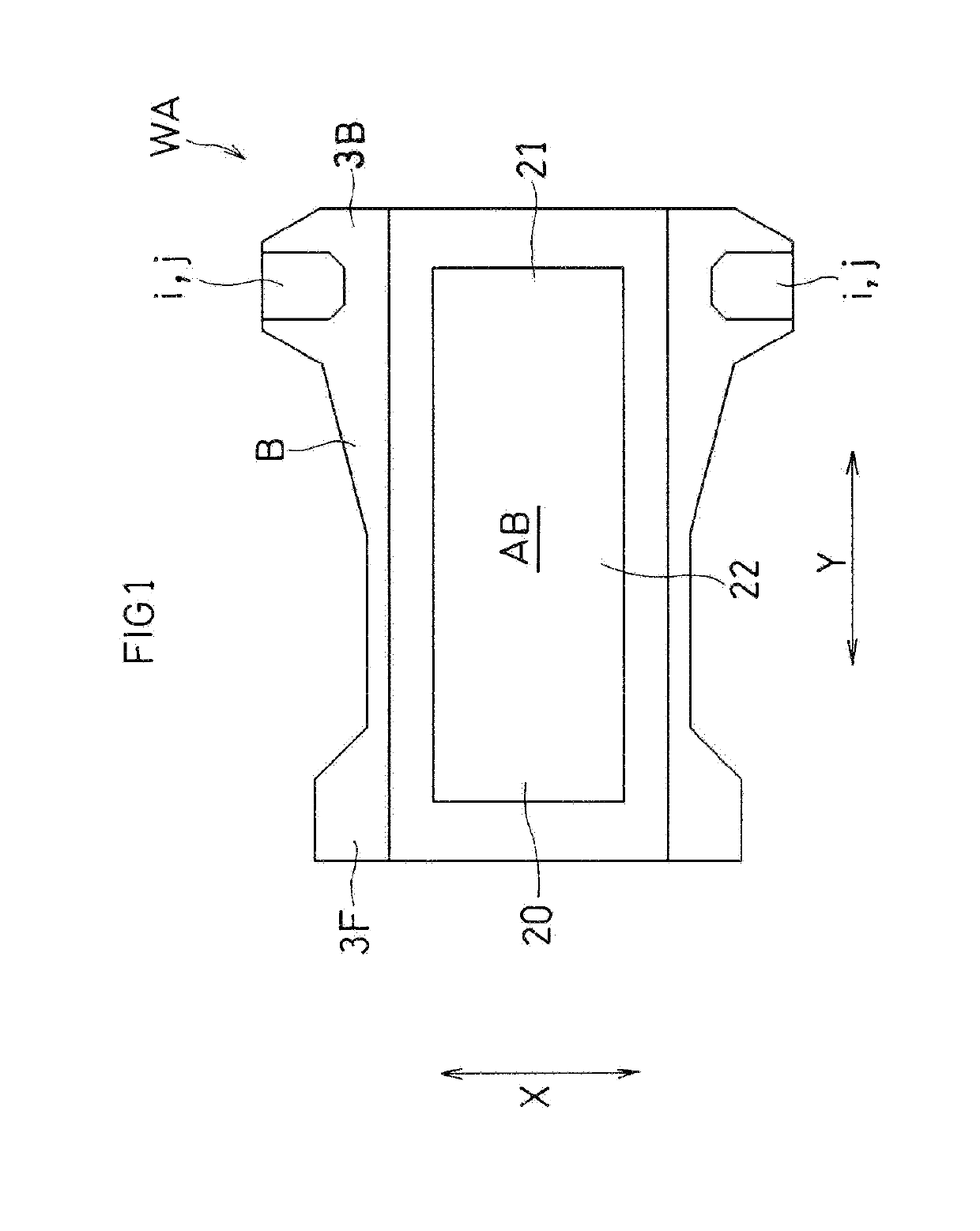
[0062]As shown in FIG. 1, the worn article WA includes an absorbent body AB and the base material B such as an external non-woven fabric. The absorbent body AB includes a front portion 20, a back portion 21 and a crotch portion 22. The front portion 20 extends in the girth direction X, covering the front ...


PUM


Abstract

A placement device for arranging parts of a disposable worn article on the base material B, wherein: a first unit U1 includes first and third pads P1 and P3 capable of accelerating and decelerating; a second unit U2 includes second and fourth pads P2 and P4 capable of accelerating and decelerating; the first unit U1 includes separate servo motors M for rotating the first pad P1 and the third pad P3 about a common axis and does not include three or more servo motors M; and the second unit U2 includes separate servo motors M for rotating the second pad P2 and the fourth pad about a common axis and does not include three or more servo motors M.

Description

TECHNICAL FIELD[0001]The present invention relates to a placement device, a placement system and a placement method for placing parts on a base material of a disposable worn article.BACKGROUND ART[0002]With disposable worn articles, it is often the case that parts such as fastening members are attached to a base material, such as a continuous material, which is to be the worn article after being processed (the first patent document).CITATION LISTPatent Literature[0003][First Patent Document] JP2013-255624 A (front page)[0004]With the conventional technique, a continuous sheet is severed into a plurality of parts, which are placed on a base material while the parts are spread apart from each other in the flow direction with a predetermined interval therebetween. In order to increase the interval between the parts to the predetermined interval, the placement device of the conventional technique uses a servo motor to rotate pads that pick up parts, and the rotation speed of the servo m...

Claims


Application Information

Patent Timeline
Patent Type & Authority Applications(United States)
IPC IPC(8): A61F13/15
CPCA61F13/15764A61F13/15756B65G47/32B65G47/846A61F13/15
Inventor INOUE, DAISUKE
Owner ZUIKO CORP
Why Eureka
Try Eureka