
Aircraft Flap Mechanism

Active Publication Date: 2019-06-13
HSUEH THOMAS
View PDF0 Cites 1 Cited by
  • Summary
  • Abstract
  • Description
  • Claims
  • Application Information

AI Technical Summary

Benefits of technology

The present invention provides an improved wing flap assembly with a lightweight and compact mechanism that allows for individual operation of each flap. The assembly includes two motors, each providing enough power to operate the flap mechanism, and a track path design that allows the flap to extend and stop half way before its downward motion, resulting in increased wing chord and aerodynamic lift without increasing induced drag.

Problems solved by technology

This type of arrangement is mechanically complicated, heavy, expensive to manufacture and maintain.
Furthermore it does not allow each flap segment to be individually activated, controlled or programmed.

Method used


Image

  • Aircraft Flap Mechanism
  • Aircraft Flap Mechanism
  • Aircraft Flap Mechanism

Examples


Embodiment Construction

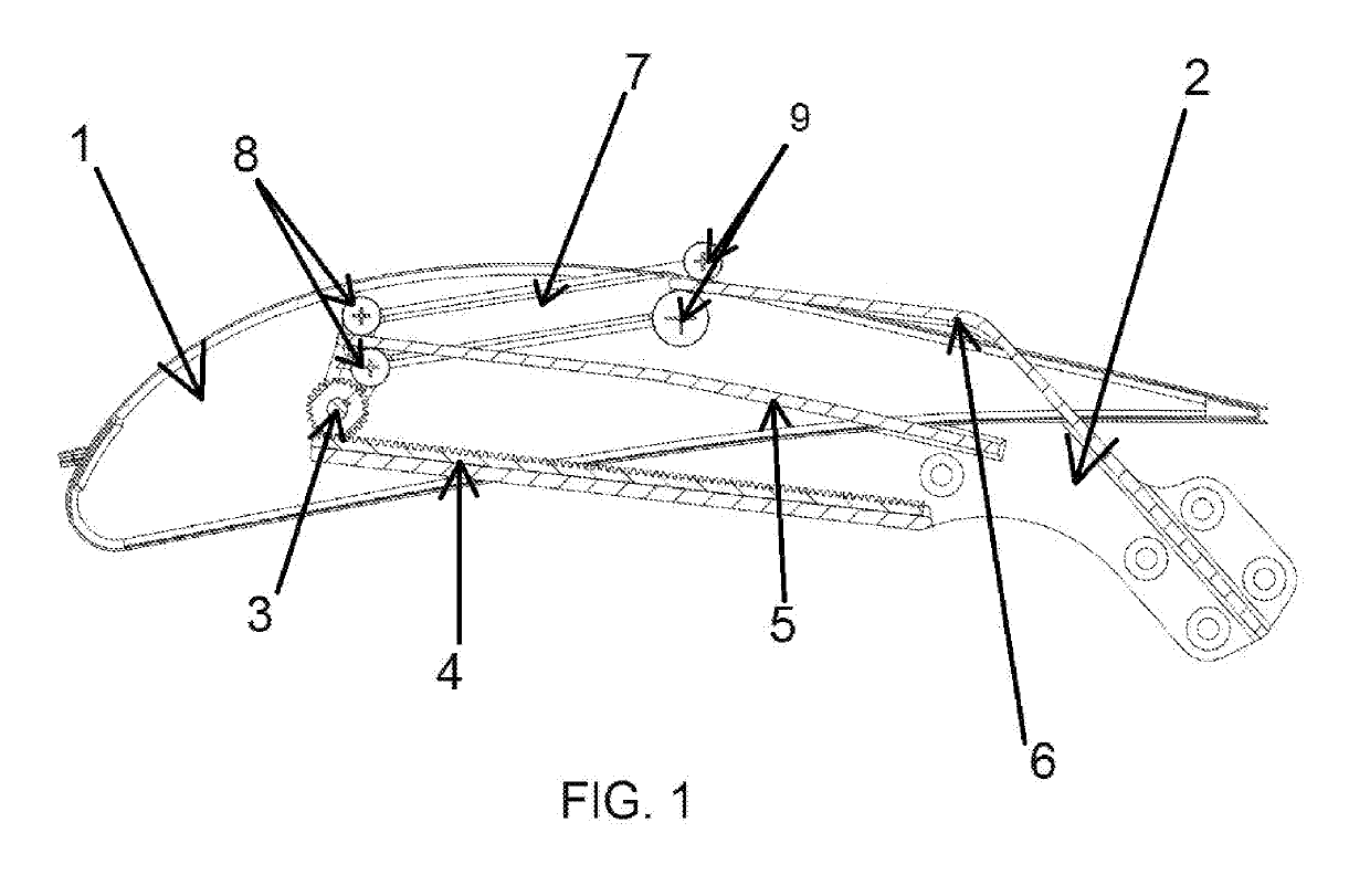
[0012]FIG. 1 shows the left side view of the flap assembly when it is retracted. Carriage 7 is attached to flap 1. Rollers 8 and 9 are fastened to carriage 7 and ride on tracks 5 and 6. Tracks 5 and 6 are integrated with track bracket 2, which is stationary and attached to the aircraft wing.

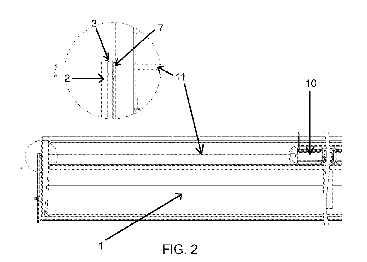
[0013]FIG. 2 shows the left bottom view of flap 1 and a detailed view of the connection between shaft 11, carriage 7, pinion gear 3 and track bracket 2. The flap mechanism is symmetrically placed on both sides of flap 1. Thus the mechanism we describe is for only one of the sides, the other side being the same.

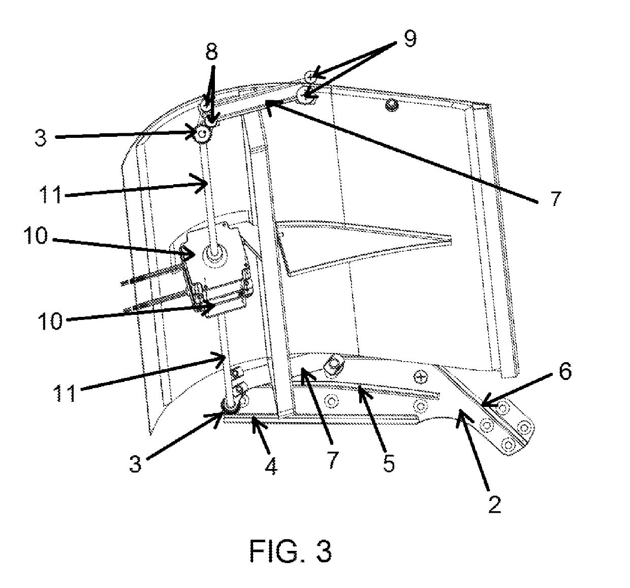
[0014]Motor 10 is placed inside the left half of flap 1 and connects to shaft 11. Shaft 11 goes horizontally through the flap 1 rib and fastens to pinion gear 3 on carriage 7. Pinion gear 3 rides on rack 4 (see FIG. 1) of track bracket 2. The arrangement is also shown in FIG. 3.

[0015]FIG. 3 shows the inside of flap 1. The two motors 10 are interconnected and installed at the middle of flap ...


PUM


Abstract

This invention relates to an aircraft flap mechanism, entirely contained within each flap, such that each flap can be activated independently of any other. The mechanism includes electric, pneumatic or hydraulic motors which activate the movement of the flaps.The invention results in a compact, light, low cost, reliable and easy to maintain mechanism. Furthermore, due to the fact that the mechanism is entirely contained within the flap it maximizes internal wing space.

Description

BACKGROUND[0001]Most aircraft utilize hydraulic actuators to provide movement to the flaps and ailerons through a system of linkages. The actuating mechanism on many commercial airliners consists of a lead screw which moves a nut up and down the length of the screw thereby driving one or more brackets attached to the control surface assembly. On aircraft having multiple flaps, each flap is actuated by its own lead screw mechanism. Each lead screw is driven by a shaft running along the length of the wing through a bevel or worm gearbox.[0002]This type of arrangement is mechanically complicated, heavy, expensive to manufacture and maintain. Furthermore it does not allow each flap segment to be individually activated, controlled or programmed. This invention describes a mechanism which overcomes the above mentioned shortcomings.SUMMARY OF THE INVENTION[0003]The general aim of the present invention is to provide an improved wing flap assembly by means of a mechanism which is light, comp...

Claims


Application Information

Patent Timeline
IPC IPC(8): B64C9/20B64C13/34
CPCB64C9/20B64C13/34B64C3/50B64C9/02B64C9/08B64C13/50B64C13/505Y02T50/10Y02T50/30
Inventor HSUEH, THOMAS
Owner HSUEH THOMAS
Learn More