Virtual Ligament Balancing

Active Publication Date: 2019-06-20
HOWMEDICA OSTEONICS CORP
View PDF0 Cites 7 Cited by
  • Summary
  • Abstract
  • Description
  • Claims
  • Application Information

AI Technical Summary

Problems solved by technology

One potential drawback of the traditional method of gap balancing is that it only takes into account the flexion gap and extension gap, without taking into account mid-flexion laxity.
Another

Method used


Image

  • Virtual Ligament Balancing
  • Virtual Ligament Balancing
  • Virtual Ligament Balancing

Examples


Embodiment Construction

[0023]Body tissues, such as ligaments, tendons, muscles, and fibrocartilage, may affect how one body portion, such as a bone of a joint, interacts with another body portion, such as another bone of the joint. Generally, if a bone or a portion of a bone undergoes frequent loading, the density of the portion of the bone loaded may be generally greater than surrounding bone that undergoes less loading.

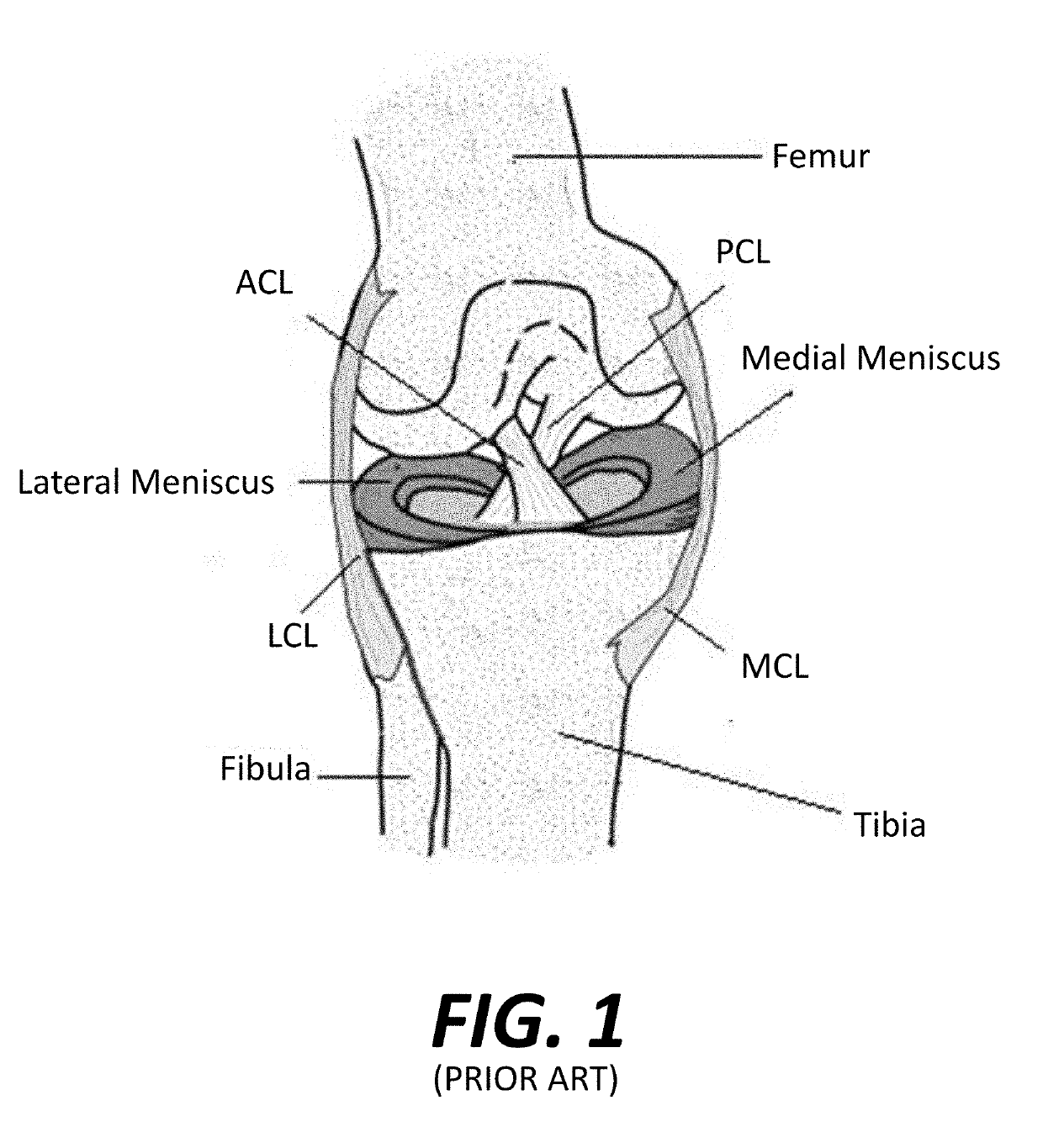
[0024]FIG. 1 is a highly simplified illustration of a typical right knee joint of a patient. The medial and lateral condyles of the distal femur articulate with respect to the medial and lateral condyles of the tibia, respectively. The articulation of the femur against the tibia is facilitated by cartilaginous tissue including the medial meniscus, which is attached the medial condyle of the tibia, and the lateral meniscus, which is attached to the lateral condyle of the tibia.

[0025]Still referring to FIG. 1, the knee joint is stabilized, in part, by four main ligaments. The anterior cruci...


PUM


Abstract

A method of generating a correction plan for a knee of a patient includes obtaining a ratio of reference bone density to reference ligament tension in a reference population. A bone of the knee of the patient may be imaged. From the image of the bone, a first dataset may be determined including at least one site of ligament attachment and existing dwell points of a medial femoral condyle and lateral femoral condyle of the patient on a tibia of the patient. Desired positions of contact in three dimensions of the femoral condyles of the patient with the tibia of the patient may be obtained by determining a relationship in which a ratio of bone density to ligament tension of the patient is substantially equal to the ratio of reference bone density to reference ligament tension.

Description

CROSS-REFERENCE TO RELATED APPLICATIONS[0001]This application claims priority to the filing date of U.S. Provisional Patent Application No. 62 / 608,050, filed Dec. 20, 2017, the disclosure of which is hereby incorporated by reference herein.BACKGROUND OF THE DISCLOSURE[0002]During a typical knee replacement procedure, a surgeon removes a portion of one or more diseased portions of the bones forming the knee joint, such as the distal femur and the proximal tibia, and one or more prosthetic components are installed onto the prepared bone in order to restore proper knee functioning. The success of a knee replacement procedure, such as a total knee replacement (“TKR”), a unicondylar knee replacement (“UKR”), or a bi-cruciate retaining knee replacement (“BCR”), may be dependent upon proper soft tissue balancing, which may also be referred to as ligament balancing or gap balancing. Proper ligament balancing may in turn be dependent upon the size and placement of the prosthetic components, ...

Claims


Application Information

Patent Timeline
IPC IPC(8): A61B5/00A61B34/10A61B90/00A61B34/20
CPCA61B5/4533A61B34/10A61B90/06A61B34/20A61B2034/105A61B34/25A61B90/36A61B2034/2065A61B5/4528A61B17/154A61B17/1764G16H20/40A61B2034/108A61B2034/256A61B6/505A61B5/4509A61B5/4842A61B5/7275A61B2034/102A61B34/30G06T7/60G06T2207/30008G06T7/0014
Inventor YILDIRIM, GOKCELIARNO, SALLYGRUCZYNSKI, MARK
Owner HOWMEDICA OSTEONICS CORP
Why Eureka
Try Eureka