
Method for spin forming lipskins

a technology of lipskin and spindle, which is applied in the field of components manufacturing, can solve the problems of significant waste of input materials, each of these manufacturing methods has and the existing manufacturing methods have fallen short of the ability to achieve the desired length of the integrated barrel and lipskin

Active Publication Date: 2019-06-20
STANDEX INT CORP
View PDF5 Cites 7 Cited by
  • Summary
  • Abstract
  • Description
  • Claims
  • Application Information

AI Technical Summary

Benefits of technology

The patent is about a new method of making lipskins that eliminates the need to waste material and reduces costs. The method uses a cylinder made of plates or rings that are welded or seamlessly joined. This cylinder is designed to improve the flow of the material and reduce the amount of waste. This method also reduces the need for rivets and labor, resulting in lower weight and improved fuel efficiency.

Problems solved by technology

For large commercial aircraft, the existing manufacturing methods have fallen short on achieving the desired length of the integrated barrel and lipskin.
Each of these manufacturing methods have fallen short in the ability to integrate the long barrel sections to the lipskin on large commercial aircraft.
Each of the methods of spinning flat plates or sheets as found in the prior art have a significant amount of waste of input material during the manufacturing process.

Method used


Image

  • Method for spin forming lipskins
  • Method for spin forming lipskins
  • Method for spin forming lipskins

Examples


Embodiment Construction

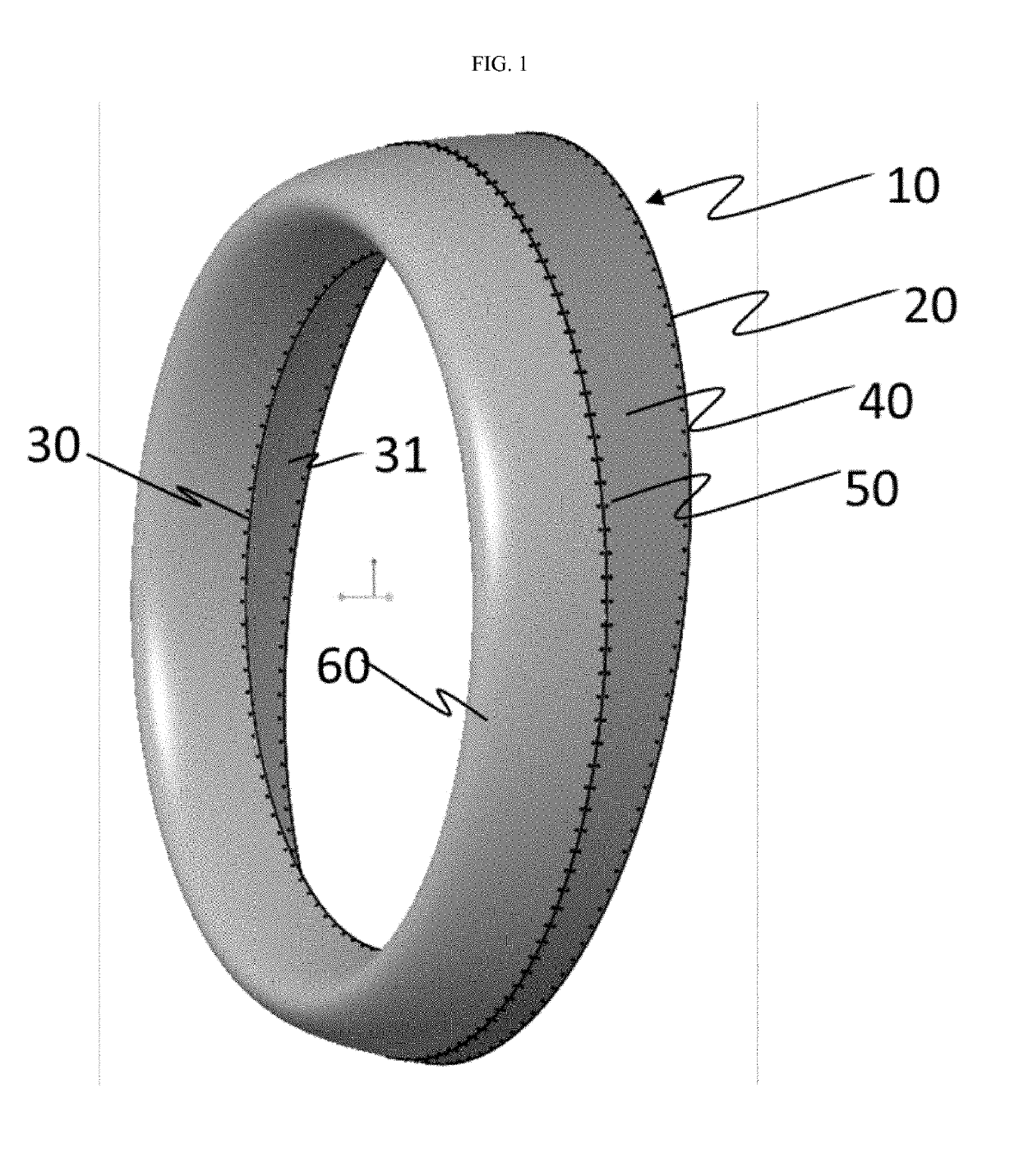
[0015]As shown in FIG. 1, a typical prior art nacelle lipskin is depicted. In this figure, inlet assembly 10 is shown. Lipskin 60 is shown riveted to outer barrel 40 along rivet line 50. Lipskin 60 is also shown attached to the inner barrel 31 (not shown for clarity) along rivet line 30. Along rivet line 20, inlet assembly 10 is attached to remaining nacelle structure (not shown) via outer barrel 40. This structure is achieved by spin forming lipskin 60 as disclosed in Wilson et al. U.S. Pat. No. 9,664,113. It would be desirable if rivet line 50 attaching lipskin 60 to outer barrel 40 could be eliminated by spin forming part 10 together.

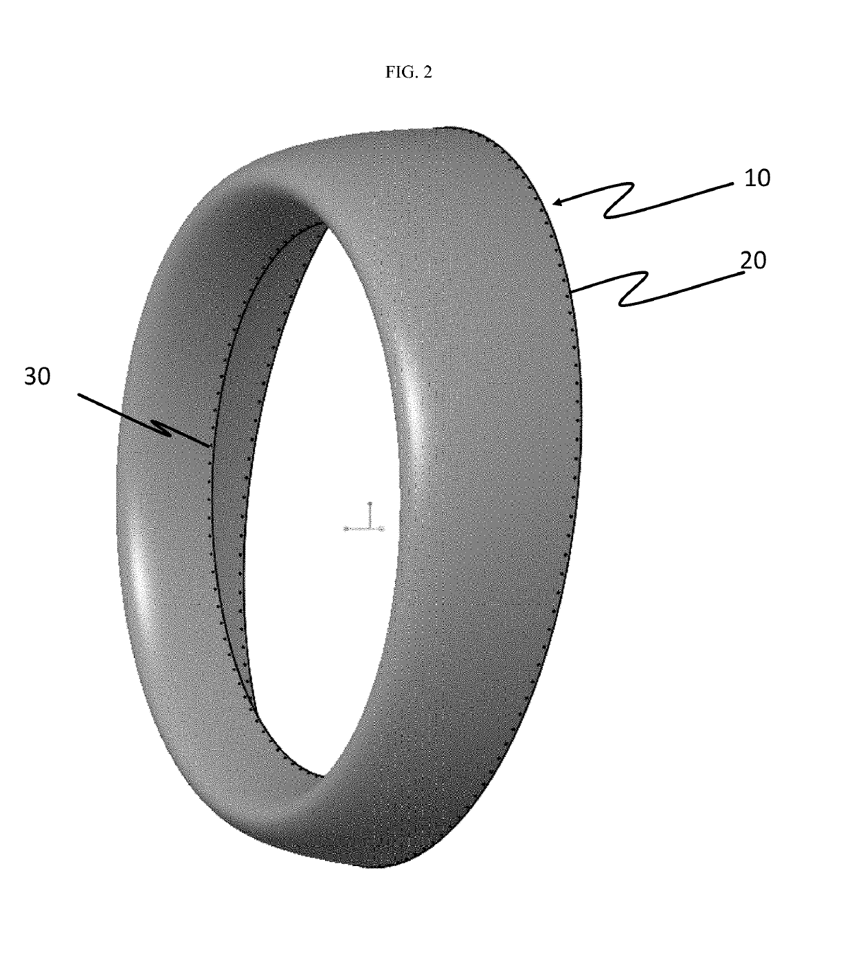
[0016]As shown in FIG. 2, the inventive method of forming the lipskin assembly 10 using unique spinning techniques eliminates the need for rivet line 50 shown in FIG. 1. Inner rivet line 30 is still required as shown.

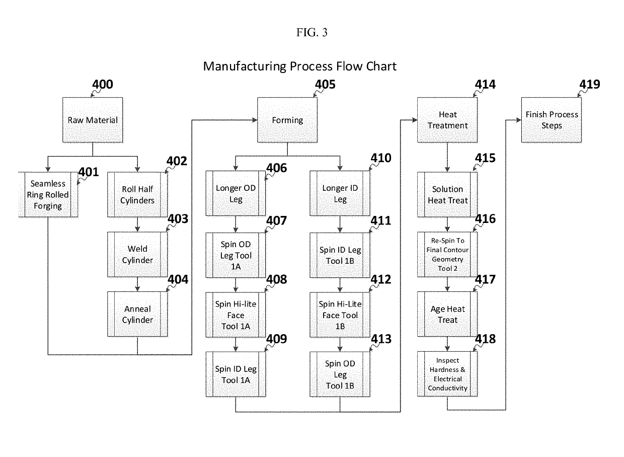
[0017]As shown in FIG. 3, the method of producing a lipskin / outer barrel integrated combination is described in detail and forms the es...


PUM

PropertyMeasurementUnit
Flow rateaaaaaaaaaa
Lengthaaaaaaaaaa
Dragaaaaaaaaaa

Abstract

Method of manufacturing of components used in the field of aviation aircraft and, specifically, an aircraft engine nacelle lipskin. Instead of spinning flat plates, this method uses spinning a cylinder, thus eliminating waste material. It also eliminates the need for rivet lines which results in better laminar flow. Further, there is a reduction of other costs in addition to reducing drag.

Description

[0001]This application claims benefit of U.S. Provisional Application Ser. No. 62 / 607,370 filed on Dec. 19, 2017, pursuant to 35 USC § 119(e).FIELD OF THE INVENTION[0002]The invention relates to the method of manufacturing of components used in the field of aviation aircraft and, specifically, an aircraft engine nacelle lipskin.BACKGROUND OF THE INVENTION[0003]The commercial airline industry continuously strives to remain competitive and profitable. Aircraft manufacturers are addressing this need through the use of more fuel-efficient aircraft designs that improve airflow and reduce drag; increase laminar flow; the use of more fuel-efficient engines; and the use of lighter weight materials in the construction of the aircraft.[0004]Improvements to aircraft engine nacelles have included the introduction of lighter weight materials such as composites and aerodynamically improved cowl lipskin designs that reduce drag and improve performance. These lipskin design changes include lengthen...

Claims


Application Information

Patent Timeline
IPC IPC(8): B21D22/14B21D53/92F02C7/04B64D29/00B64D33/02B64F5/60
CPCB21D22/14B21D53/92F02C7/04B64D29/00B64D33/02B64F5/60F05D2220/323F05D2230/232F05D2230/26F05D2230/41F05D2230/30F05D2300/6034B21D53/84C22F1/04B64C7/02B64D2033/0273B64F5/00Y02P70/50Y02T50/60C21D9/00
Inventor MORGANTI, RICHARD J.
Owner STANDEX INT CORP
Learn More