Combustion apparatus

a technology of combustion apparatus and compression allowance, which is applied in the direction of combustion types, indirect heat exchangers, lighting and heating apparatus, etc., can solve the problems of preventing the attempt to reduce the cost, and achieve the effect of reducing the cost, improving the workability of assembly work, and reducing the compression allowan

Active Publication Date: 2019-06-20
RINNAI CORP
View PDF0 Cites 6 Cited by
  • Summary
  • Abstract
  • Description
  • Claims
  • Application Information

AI Technical Summary

Benefits of technology

[0006]According to this invention, the packing is fixed in position by the outside projection and the inside projection. Therefore, even without forming a packing mounting groove in the body flange part, the packing can be fixed in position. As a result, it becomes possible to manufacture the burner body in sheet metal, thereby attaining a cost reduction. Further, as a result of contact of the outside projection and the inside projection with the body flange part, the compression allowance of the packing can be appropriately managed, and the workability in assembling work can be improved.
[0007]The combustion plate may be provided with a member having formed therein an inside projection. However, in case the combustion plate is provided with a distribution plate having formed therein a multiplicity of distribution holes for introducing the air-fuel mixture into the air-fuel mixture ejection part, it is preferable to form by bending the inside projection in an outer rim of the distribution plate. According to this arrangement, the distribution plate can be made to serve the dual purpose as a material in which the inside projection is formed, thereby reducing the number of constituting parts.
[0008]In this invention, preferably the combustion plate flange part may comprise a claw part formed by bending a part of the outer rim of the combustion plate flange part such that the claw part is inserted into a hole formed in the packing. According to this arrangement, the positioning accuracy of the packing can be improved.

Problems solved by technology

This solution will result in an obstacle to an attempt to reduce the cost.

Method used


Image

  • Combustion apparatus
  • Combustion apparatus
  • Combustion apparatus

Examples


Embodiment Construction

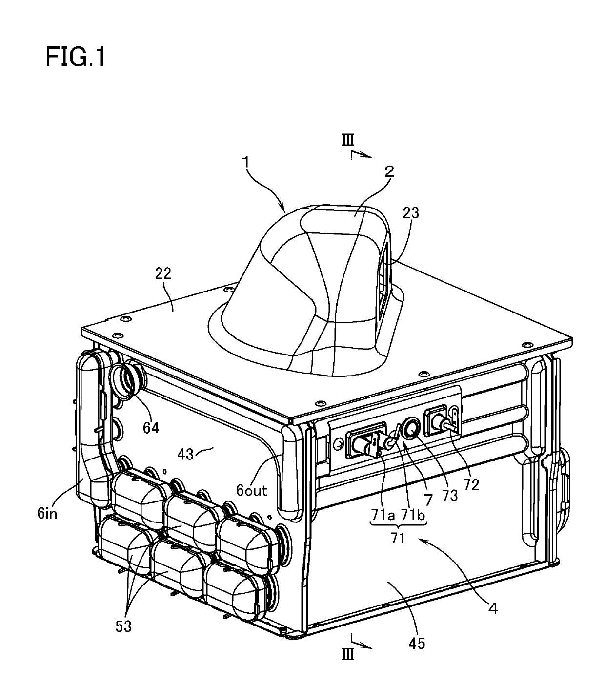
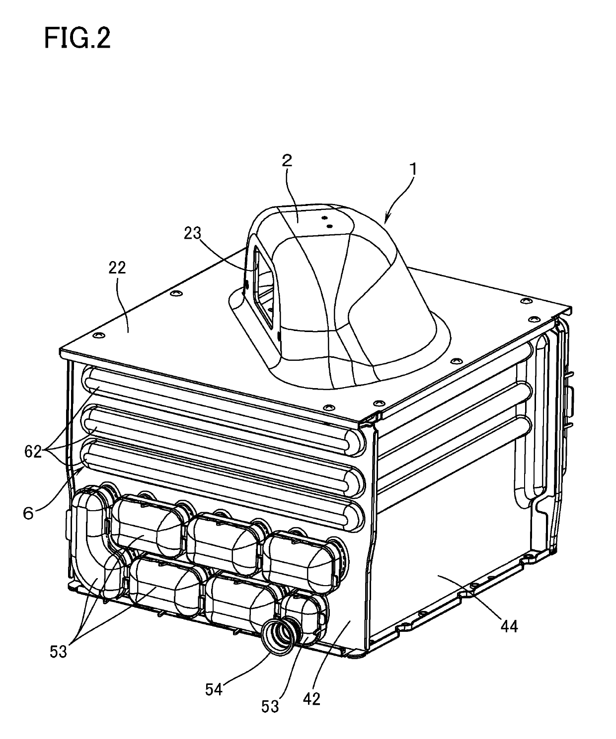
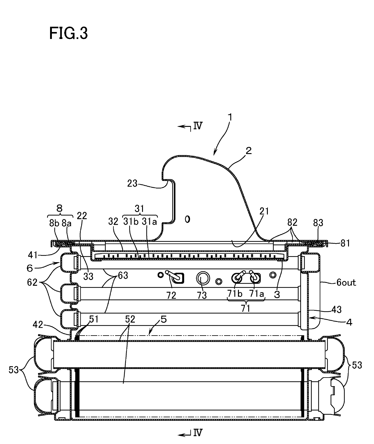
[0015]With reference to FIG. 1 to FIG. 4, a combustion apparatus according to an embodiment of this invention is provided with: a burner 1 made up of a burner body 2 which is supplied inside thereof with air-fuel mixture (mixture gas of fuel gas and primary air), and a combustion plate 3, made of a sheet metal and having an air-fuel mixture ejection part 31, the combustion plate 3 covering a downward open surface 21 of the burner body 2; and a combustion box 4 of a sheet-metal make which has, on a perimeter of an upper end, a combustion box flange part 41 to be connected to a body flange part 22 which encloses the open surface 21 of the burner body 2. The combustion box 4 contains, inside thereof, a heat exchanger 5 for supplying hot water.

[0016]On a side surface of the portion swollen upward in the central part of the burner body 2, there is provided an inlet port 23 to which is connected a fan (not illustrated) for supplying air-fuel mixture. The combustion plate 3 has a large ope...


PUM


Abstract

A combustion apparatus has a burner including a burner body and a combustion plate, as well as a combustion box. A combustion plate flange part projects outward beyond an inner rim of a body flange part and beyond an inner rim of a combustion box flange part. The combustion box has, on a perimeter of one end, the combustion box flange part, adapted to be connected to the body flange part enclosing an open surface of the burner body. The combustion plate is provided with an inside projection which is erected, by bending, toward the body flange part so as to face the inner rim of the packing such that, in a state in which the combustion box flange part is connected to the body flange part, the outside projection and the inside projection are in contact with the body flange part.

Description

TECHNICAL FIELD[0001]The present invention relates to a combustion apparatus comprising: a burner made up of a burner body which is supplied therein with air-fuel mixture, and a combustion plate which covers an open surface of the burner body and which has an air-fuel mixture ejection part; and a combustion box which has, on a perimeter of one end, a combustion box flange part, adapted to be connected to a body flange part enclosing the open surface of the burner body, the combustion box containing therein a heat exchanger.BACKGROUND ART[0002]As this kind of combustion apparatus, there is known an apparatus in JP-A 2017-78542 having the following features. In other words, the combustion apparatus includes: a combustion plate flange part disposed on a perimeter of the combustion plate in a manner to project outward beyond an inner rim of the body flange part and beyond an inner rim of the combustion box flange part, and also in a manner that an outer rim of the combustion plate flang...

Claims


Application Information

Patent Timeline
Patent Type & Authority Applications(United States)
IPC IPC(8): F24H1/14F24H9/02F24H9/18F23D14/14F28F1/14
CPCF24H1/145F24H9/02F24H9/1836F23D14/14F28F1/14F28F1/22F28D2021/0024F28D7/1615F28F2215/12F23D14/02F23D2203/1017F23D2203/106F23D2900/00019
Inventor ONO, TAKAHIRO
Owner RINNAI CORP
Why Eureka
Try Eureka